CRD4525-Q1 Cirrus Logic Inc, CRD4525-Q1 Datasheet - Page 51
CRD4525-Q1
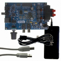
Manufacturer Part Number
CRD4525-Q1
Description
REFERENCE BOARD FOR CS4525 PWM
Manufacturer
Cirrus Logic Inc
Series
Popguard®r
Specifications of CRD4525-Q1
Amplifier Type
Class D
Output Type
2-Channel (Stereo)
Max Output Power X Channels @ Load
15W x 2 @ 8 Ohm
Voltage - Supply
12 V ~ 18 V
Operating Temperature
0°C ~ 70°C
Board Type
Fully Populated
Utilized Ic / Part
CS4525
Lead Free Status / RoHS Status
Contains lead / RoHS non-compliant
Other names
598-1586


DS726PP3
6.1.10 Headphone Detection & Hardware Mute Input
6.1.9.2
When using a PWM amplifier in a system containing an AM tuner, it is possible that the PWM switch rate
conflicts with the desired tuning frequency of the AM tuner. To overcome this effect, the CS4525 includes
a PWM switch rate shift feature.
The feature adjusts the PWM switching frequency and quantization levels to remove interference when
the desired tuning frequency of an AM tuner is positioned near a harmonic of the PWM switching rate.
This feature is enabled by setting the FreqShift bit in the Clock Config register. When this feature is en-
abled, the output switch rate is lowered and the quantization levels are increased as shown in
below.
The nominal PWM switching frequencies and quantization levels are discussed in
Sample Rate Converters” on page
The CS4525 includes a configurable HP_DETECT/MUTE input pin which can be used as a hardware
mute input or a headphone detection input. The function of this pin is set by the HP/Mute bit in the Clock
Config register.
When configured as a mute input pin, all PWM modulators and the AUX_SDOUT signal will be placed in
a mute state when the pin is active.
When configured as a headphone detect input pin and the HP_DETECT/MUTE input is active, the
PWM_SIG1 and PWM_SIG2 output pins can output audio from channel 1 and channel 2 respectively re-
gardless of the setting of the PWMDSel[1:0] bits. The OUT1 - OUT4 PWM driver outputs will mute by out-
putting a non-modulated 50% duty cycle signal. While the headphone detect input signal is active, the
channel mixing, 2-way crossover, and bass management features will all be disabled regardless of the
settings of the LChMix[1:0], En2Way, and BassMgr[2:0] bits, respectively. It should be noted that the right
channel’s channel mixing is not affected by the headphone detection input signal and will always output
as dictated by the RChMix[1:0] bits. See
Control” on page
When configured as a headphone detect input pin and the HP_DETECT/MUTE input is inactive, the
OUT1 - OUT4 driver outputs will output audio according to the channel mixer and bass manager bits’ set-
tings, and the PWM_SIG output pins will mute by outputting a non-modulated 50% duty cycle.
Referenced Control
FreqShift..............................
PWM AM Frequency Shift
SYS_CLK Frequency
Table 11. PWM Output Switching Rates and Quantization Levels
Supplied XTAL or
42, and
18.432 MHz
24.576 MHz
27.000 MHz
Register Location
“AM Frequency Shifting (FreqShift)” on page 70
“Bass Management” on page 35
58.
PWM Switch Rate
“Channel Mixer” on page
329.143 kHz
341.300 kHz
375 kHz
for more information.
Quantization Levels
30,
“2-Way Crossover & Sensitivity
56
72
72
“PWM Modulators and
CS4525
Table 11
51
Related parts for CRD4525-Q1
Image
Part Number
Description
Manufacturer
Datasheet
Request
R

Part Number:
Description:
Development Kit
Manufacturer:
Cirrus Logic Inc
Datasheet:
Part Number:
Description:
Development Kit
Manufacturer:
Cirrus Logic Inc
Datasheet:


Part Number:
Description:
High-efficiency PFC + Fluorescent Lamp Driver Reference Design
Manufacturer:
Cirrus Logic Inc
Datasheet:
Part Number:
Description:
Development Kit
Manufacturer:
Cirrus Logic Inc
Datasheet:
Part Number:
Description:
Development Kit
Manufacturer:
Cirrus Logic Inc
Datasheet:

Part Number:
Description:
Development Kit
Manufacturer:
Cirrus Logic Inc
Datasheet:
Part Number:
Description:
Development Kit
Manufacturer:
Cirrus Logic Inc
Datasheet:
Part Number:
Description:
Development Kit
Manufacturer:
Cirrus Logic Inc
Datasheet:
Part Number:
Description:
Audio Modules & Development Tools EvalBd 30W Qd Hlf- Brdg Dig Amp Pwr Stg
Manufacturer:
Cirrus Logic Inc
Datasheet:

Part Number:
Description:
EVALUATION BOARD FOR CS8427
Manufacturer:
Cirrus Logic Inc
Datasheet:

Part Number:
Description:
BOARD EVAL FOR CS8416 RCVR
Manufacturer:
Cirrus Logic Inc
Datasheet:

Part Number:
Description:
EVALUATION BOARD FOR CS8420
Manufacturer:
Cirrus Logic Inc
Datasheet:

Part Number:
Description:
KIT DEVELOPMENT EP9315 ARM9
Manufacturer:
Cirrus Logic Inc
Datasheet: