EVAL-AD7674CB Analog Devices Inc, EVAL-AD7674CB Datasheet - Page 6
EVAL-AD7674CB
Manufacturer Part Number
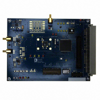
EVAL-AD7674CB
Description
BOARD EVAL FOR AD7674
Manufacturer
Analog Devices Inc
Series
PulSAR®r
Specifications of EVAL-AD7674CB
Number Of Adc's
1
Number Of Bits
18
Sampling Rate (per Second)
800k
Data Interface
Serial, Parallel
Inputs Per Adc
1 Differential
Input Range
0 ~ 5 V
Power (typ) @ Conditions
126mW @ 800kSPS
Voltage Supply Source
Analog and Digital
Operating Temperature
-40°C ~ 85°C
Utilized Ic / Part
AD7674
Lead Free Status / RoHS Status
Contains lead / RoHS non-compliant


EVAL-AD76XXCB
Figure 11 is the setup screen where ADC device selection, test
type, input voltage range, sample rate and number of samples
are selected.
DC TESTING - HISTOGRAM
Figure 12 is the histogram screen, which tests the code
distribution for DC input and computes the mean and standard
deviation or transition noise. To perform a histogram test, select
“Histogram” from the test selection window and click on the
“Start” radio button. Note: a histogram test can be performed
without an external source since the evaluation board has a
buffered V
at 0V for bipolar devices. To test other DC values, apply a source
to the J1/J2 inputs. It is advised to filter the signal to make the
DC source noise compatible with that of the ADC. C26/C41
provide this filtering.
AC TESTING
Figure 13 is the FFT screen, which performs an FFT on the
captured data and computes the SNR, SINAD, THD and SFDR.
Figure 14 is the time domain representation of the output. To
perform an AC test, apply a sinusoidal signal to the evaluation
board at the SMB inputs J1 for IN+ and J2 for IN-. Low
distortion, better than 100dB, is required to allow true
evaluation of the part. One possibility is to filter the input signal
from the AC source. There is no suggested bandpass filter but
consideration should be taken in the choice. Furthermore, if
using a low frequency bandpass filter when the full-scale input
range is more than a few Vpp, it is recommended to use the on
board amplifiers to amplify the signal, thus preventing the filter
from distorting the input signal.
REF
/2 source at the ADC input for unipolar parts and
Rev. PrW | Page 6 of 22
DECIMATED AC TESTING (AVERAGING)
The AC performances can be evaluated after digital filtering
with enhanced resolution of up to 32 bits. Figure 15 is the FFT
screen when decimation is used. Additional bits of resolution
are attained when over sampling by:
where , N = number of bits and 4
DRATIO to the amount of over sampling desired. When using
decimation, the test duration increases with the larger number
of samples taken. The decimated test requires the EVAL-
CONTROL-BRD3.
SERIAL PROGRAMMABEL PORT (AD7610,
AD7612, AD7631, AD7634, AD7951)
Figure 16 is a screen showing the flexible serial programmable
port (SPP) used on the AD7610, AD7612, AD7631, AD7634 and
AD7951 iCMOS ADCs. The SPP can be used in any serial mode
and allows the configuration of: unipolar and bipolar input
ranges, mode selection, straight binary or 2’s complement
output coding, and power down. The software demo allows two
different configurations and alternates between these two every
ten samples. To use just one range or mode, simply enter the
same values into both “A” and “B” configuration windows. Note
that when using the unipolar input ranges, a common mode
voltage must be provided externally (DC coupled) as the board
is configured with the common mode = 0V
f
OVERSAMPLE
=
4
N
Preliminary Technical Data
f *
SAMPLE
N
.= the DRATIO. Set the
Related parts for EVAL-AD7674CB
Image
Part Number
Description
Manufacturer
Datasheet
Request
R

Part Number:
Description:
ENERCHIP CC EVAL KIT
Manufacturer:
Cymbet Corporation
Datasheet:

Part Number:
Description:
BOARD EVAL FOR AD976
Manufacturer:
Analog Devices Inc
Datasheet:

Part Number:
Description:
BOARD EVAL FOR ADXL345
Manufacturer:
Analog Devices Inc
Datasheet:

Part Number:
Description:
ENERCHIP CC SEH EVAL KIT
Manufacturer:
Cymbet Corporation
Datasheet:

Part Number:
Description:
ENERCHIP EP ENERGY HARVEST EVAL
Manufacturer:
Cymbet Corporation
Datasheet:

Part Number:
Description:
EVAL BOARD FOR TW6864-LB2-GR
Manufacturer:
Intersil
Datasheet:
Part Number:
Description:
EVAL BOARD FOR TW8816-LB3-GR
Manufacturer:
Intersil
Datasheet:
Part Number:
Description:
EVAL BOARD FOR TW8817-TA3-GRS
Manufacturer:
Intersil
Datasheet:

Part Number:
Description:
EVALUATION MODULE FOR ADUM4160
Manufacturer:
Analog Devices Inc
Datasheet:

Part Number:
Description:
BOARD EVALUATION ADCMP581BCP
Manufacturer:
Analog Devices Inc
Datasheet:
Part Number:
Description:
BOARD EVALUATION ADM1041
Manufacturer:
Analog Devices Inc
Datasheet:

Part Number:
Description:
EVAL BOARD FOR STM32F107VCT
Manufacturer:
STMicroelectronics
Datasheet:
Part Number:
Description:
BOARD EVAL FOR AD1954
Manufacturer:
Analog Devices Inc
Datasheet:
Part Number:
Description:
BOARD EVAL FOR AD1955
Manufacturer:
Analog Devices Inc
Datasheet:

Part Number:
Description:
BOARD EVAL FOR AD7655
Manufacturer:
Analog Devices Inc
Datasheet: