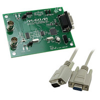
MAX7456EVKIT+ Maxim Integrated Products, MAX7456EVKIT+ Datasheet - Page 37

MAX7456EVKIT+
Manufacturer Part Number
MAX7456EVKIT+
Description
KIT EVAL FOR MAX7456
Manufacturer
Maxim Integrated Products
Specifications of MAX7456EVKIT+
Main Purpose
Video, On-Screen Display (OSD)
Embedded
Yes, MCU, 16-Bit
Utilized Ic / Part
MAX7456
Primary Attributes
NTSC/PAL single-channel monochrome on-screen display(OSD) with integrated video driver
Secondary Attributes
GUI, SPI Interfaces
Lead Free Status / RoHS Status
Lead free / RoHS Compliant
Read address = BxH.
Read/write access: read only.
Read address = CxH.
Read/write access: read only.
NA = Not applicable.
X = Don’t care.
NA = Not applicable.
X = Don’t care.
Display Memory Data Out Register (DMDO)
BIT
7–0
BIT
7, 6
5, 4
3, 2
1, 0
Character Memory Data Out Register
DEFAULT
DEFAULT
______________________________________________________________________________________
NA
NA
NA
NA
NA
Single-Channel Monochrome On-Screen
Character Address or Character Attribute byte to be read from the display memory.
8-Bit Operation Mode (DMM[6] = 1):
If DMAH[1] = 0, the content is to be interpreted as a Character Address byte, where
If DMAH[1] = 1, the content is to be interpreted as a Character Attribute byte where
16-Bit Operation Mode (DMM[6] = 0):
The content is to be interpreted as a Character Address byte, where
followed by a Character Attribute byte, where
Leftmost pixel. 00 = Black, 10 = White, 01 or 11 = Transparent (see Figure 11)
Left center pixel. 00 = Black, 10 = White, 01 or 11 = Transparent (see Figure 11)
Right center pixel. 00 = Black, 10 = White, 01 or 11 = Transparent (see Figure 11)
Rightmost pixel. 00 = Black, 10 = White, 01 or 11 = Transparent (see Figure 11)
Bits 7–0 = Character Address bits, CA[7:0] (Figure 12)
Bit 7 = Local Background Control bit, LBC (see Figure 24 and Table 4)
Bit 6 = Blink bit, BLK
Bit 5 = Invert bit, INV (see Figure 24)
Bit 4–0 = 0
The LBC, BLK, and INV bits are described in the Display Memory Mode register.
Bits 7–0 = CA[7:0] (see Figure 12)
Bit 7 = 0
Bit 6 = Local Background Control bit, LBC (see Figure 24 and Table 4)
Bit 5 = Blink bit, BLK
Bit 4 = Invert bit, INV (see Figure 24)
Bit 3–0 = 0
The LBC, BLK, and INV bits are described in the Display Memory Mode register.
Display with Integrated EEPROM
(CMDO)
To write to this register the following condition must be
met:
DMM[2] = 0, the display memory is not in the process
of being cleared.
To write to this register, the following conditions must
be met:
1) STAT[5] = 0, the character memory (NVM) is not
2) VM0[3] = 0, the OSD is disabled.
busy.
FUNCTION
FUNCTION
37


