LMK03200EVAL National Semiconductor, LMK03200EVAL Datasheet - Page 27
LMK03200EVAL
Manufacturer Part Number
LMK03200EVAL
Description
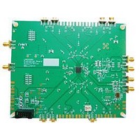
BOARD EVALUATION LMK03200
Manufacturer
National Semiconductor
Specifications of LMK03200EVAL
Main Purpose
Timing, Clock Conditioner
Embedded
No
Utilized Ic / Part
LMK03200
Primary Attributes
3 LVDS & 5 LVPECL Outputs, Integrated PLL & VCO
Secondary Attributes
3.15 V ~ 3.45 V Supply
Silicon Manufacturer
National
Silicon Core Number
LMK03200
Kit Application Type
Clock & Timing
Application Sub Type
Precision Clock Conditioner
Kit Contents
Board, Cable
Lead Free Status / RoHS Status
Lead free / RoHS Compliant


2.7 Register R11
This register only has one bit and only needs to be pro-
grammed in the case that the phase detector frequency is
greater than 20 MHz and digital lock detect is used. Other-
wise, it is automatically defaulted to the correct values.
2.7.1 DIV4 -- High Phase Detector Frequencies and Lock
Detect
This bit divides the frequency presented to the digital lock de-
tect circuitry by 4. It is necessary to get a reliable output from
the digital lock detect output in the case of a phase detector
frequency greater than 20 MHz.
2.8 Register R13
2.8.1 VCO_C3_C4_LF [3:0] -- Value for Internal Loop Filter
Capacitors C3 and C4
These bits control the capacitor values for C3 and C4 in the
internal loop filter.
2.8.2 VCO_R3_LF [2:0] -- Value for Internal Loop Filter
Resistor R3
These bits control the R3 resistor value in the internal loop
filter. The recommended setting for VCO_R3_LF[2:0] = 0 for
optimum phase noise and jitter.
VCO_C3_C4_LF [3:0]
DIV4
VCO_R3_LF[2:0]
0
1
12 to 15
5 to 7
10
11
0
1
2
3
4
5
6
7
8
9
0
1
2
3
4
Phase Detector Frequency
Phase Detector Frequency > 20 MHz
Digital Lock Detect Circuitry Mode
0 (default)
Divided by 4
Not divided
C3 (pF)
Loop Filter Capacitors
Low (~600 Ω) (default)
100
100
100
150
150
50
50
50
0
0
0
R3 Value (kΩ)
Invalid
Invalid
≤
10
20
30
40
20 MHz (default)
10 (default)
C4 (pF)
110
110
110
160
160
110
60
10
10
60
60
27
2.8.3 VCO_R4_LF [2:0] -- Value for Internal Loop Filter
Resistor R4
These bits control the R4 resistor value in the internal loop
filter. The recommended setting for VCO_R4_LF[2:0] = 0 for
optimum phase noise and jitter.
2.8.4 OSCin_FREQ [7:0] -- Oscillator Input Calibration
Adjustment
These bits are to be programmed to the OSCin frequency. If
the OSCin frequency is not an integral multiple of 1 MHz, then
round to the closest value.
2.9 Register R14
2.9.1 PLL_R [11:0] -- R Divider Value
These bits program the PLL R Divider and are programmed
in binary fashion. Any changes to PLL_R require R15 to be
programmed again while 0_DELAY_MODE = 0 to active the
frequency calibration routine.
0
0
0
0
1
.
.
OSCin_FREQ [7:0]
VCO_R4_LF[2:0]
0
0
0
0
1
.
.
201 to 255
0
0
0
0
1
.
.
5 to 7
200
10
...
...
0
1
2
3
4
1
2
0
0
0
0
1
.
.
PLL_R [11:0]
0
0
0
0
1
.
.
0
0
0
0
1
.
.
0
0
0
0
1
.
.
0
0
0
0
1
.
.
0
0
0
1
1
Low (~200 Ω) (default)
.
.
OSCin Frequency
10 MHz (default)
0
0
0
0
1
.
.
R4 Value (kΩ)
200 MHz
0
0
1
1
1
.
.
Invalid
1 MHz
2 MHz
Invalid
10
20
30
40
...
...
0
1
0
0
1
.
.
PLL R Divide
10 (default)
www.national.com
Invalid
Value
4095
...
...
1
2
Related parts for LMK03200EVAL
Image
Part Number
Description
Manufacturer
Datasheet
Request
R

Part Number:
Description:
Precision 0-delay Clock Conditioner With Integrated Vco
Manufacturer:
National Semiconductor Corporation
Datasheet:

Part Number:
Description:
National Semiconductor [8-Bit D/A Converter]
Manufacturer:
National Semiconductor
Datasheet:
Part Number:
Description:
National Semiconductor [Media Coprocessor]
Manufacturer:
National Semiconductor
Datasheet:
Part Number:
Description:
Digitally Controlled Tone and Volume Circuit with Stereo Audio Power Amplifier, Microphone Preamp Stage and National 3D Sound
Manufacturer:
National Semiconductor
Datasheet:
Part Number:
Description:
Digitally Controlled Tone and Volume Circuit with Stereo Audio Power Amplifier, Microphone Preamp Stage and National 3D Sound
Manufacturer:
National Semiconductor
Datasheet:
Part Number:
Description:
AC97 Rev 2 Codec with Sample Rate Conversion and National 3D Sound
Manufacturer:
National Semiconductor
Part Number:
Description:
Manufacturer:
National Semiconductor
Datasheet:
Part Number:
Description:
Manufacturer:
National Semiconductor
Datasheet:
Part Number:
Description:
General Purpose, Low Voltage, Low Power, Rail-to-Rail Output Operational Amplifiers
Manufacturer:
National Semiconductor
Datasheet:
Part Number:
Description:
8-bit 20 MSPS flash A/D converter.
Manufacturer:
National Semiconductor
Datasheet:
Part Number:
Description:
Low Noise Quad Operational Amplifier
Manufacturer:
National Semiconductor
Datasheet:
Part Number:
Description:
Quad Differential Line Receivers
Manufacturer:
National Semiconductor
Datasheet:
Part Number:
Description:
Quad High Speed Trapezoidal? Bus Transceiver
Manufacturer:
National Semiconductor
Datasheet:
Part Number:
Description:
Dual Line Receiver
Manufacturer:
National Semiconductor
Datasheet: