ADV212-HD-EB Analog Devices Inc, ADV212-HD-EB Datasheet - Page 23
ADV212-HD-EB
Manufacturer Part Number
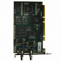
ADV212-HD-EB
Description
BOARD EVALUATION FOR ADV212-HD
Manufacturer
Analog Devices Inc
Datasheet
1.ADV212BBCZRL-115.pdf
(44 pages)
Specifications of ADV212-HD-EB
Main Purpose
Video, Video Processing
Embedded
Yes, FPGA / CPLD
Utilized Ic / Part
ADV212-HD
Primary Attributes
1080i and 720p SDI Compatible, 32/64-bit, 33/66 MHz PCI Card
Secondary Attributes
GUI, JPEG2000 Video Codec
Lead Free Status / RoHS Status
Contains lead / RoHS non-compliant


Pin No.
101
115
103
102
53
44, 43, 29,
31, 32, 18
to 20, 22,
21, 7, 10
41
42
54
94
108
98
116
109
3, 8, 40, 84,
120
121-Ball Package
Location
K2
L5
K4
K3
E9
D11, D10,
C7, C9, C10,
B7, B8, B9,
B11, B10,
A7, A10
D8
D9
E10
J6
K9
J10
L6
K10
A3, A8, D7,
H7, L10
Pin No.
122
123
109
110
60
46 to 48,
34 to 36,
22 to 24,
9 to 11
58
59
57
120
119
118
141
130
18, 19, 30,
31, 42, 43,
102, 103,
114, 115,
126, 127,
142
144-Ball Package
Location
L2
L3
K1
K2
E12
D10 to D12,
C10 to C12,
B10 to B12,
A9 to A11
E10
E11
E9
K12
K11
K10
M9
L10
B6, B7, C6,
C7, D6, D7,
J6, J7, K6,
K7, L6, L7,
M10
Mnemonic
SCOMM3
SCOMM2
SCOMM1
SCOMM0
VCLK
VDATA[11:0]
VSYNC
VFRM
HSYNC
VRDY
FIELD
VSTRB
TCK
TRS
TMS
TDI
TDO
VDD
Rev. B | Page 23 of 44
Pins
Used
1
12
1
1
1
1
1
1
1
1
5/13
Type
I
O
I
O
I
I/O
I/O
I/O
O
I/O
I
I
I
I
I
O
V
Description
Serial Communication. For internal use only.
This pin should be tied low via a 10 kΩ
resistor.
Serial Communication. For internal use only.
This pin should be tied low via a 10 kΩ
resistor.
Serial Communication. For internal use only.
This pin should be tied low via a 10 kΩ
resistor.
Serial Communication. This pin should be tied
low via a10 kΩ resistor.
Video Data Clock. This pin must be supplied if
video data is input/output on the VDATA bus.
Video Data. Unused pins should be pulled
down via a 10 kΩ resistor.
Vertical Sync for Video Mode.
Raw Pixel Mode Framing Signal. When this pin
is asserted high, it indicates the first sample of
a tile.
Horizontal Sync for Video Mode.
Raw Pixel Mode Ready Signal.
Field Sync for Video Mode.
Raw Pixel Mode Transfer Strobe.
JTAG Clock. If not used, this pin should be
connected to ground via a pull-down resistor.
JTAG Reset. If the JTAG is used, this pin must
be toggled low to high. If JTAG is not used,
this pin must be held low.
JTAG Mode Select. If JTAG is used, connect a
10 kΩ pull-up resistor to this pin. If not used,
this pin should be connected to ground via
a pull-down resistor.
JTAG Serial Data Input. If JTAG is used, connect
a 10 kΩ pull-up resistor to this pin. If JTAG is
not used, this pin should be connected to
ground via a pull-down resistor.
JTAG Serial Data Output. If this pin is not used,
do not connect it.
Positive Supply for Core.
ADV212
Related parts for ADV212-HD-EB
Image
Part Number
Description
Manufacturer
Datasheet
Request
R

Part Number:
Description:
BOARD EVAL FOR ADV212 CODEC
Manufacturer:
Analog Devices Inc
Datasheet:

Part Number:
Description:
±1.7g Dual-Axis IMEMS Accelerometer Evaluation Board
Manufacturer:
Analog Devices Inc
Datasheet:
Part Number:
Description:
Inertial Sensor Evaluation System
Manufacturer:
Analog Devices Inc
Datasheet:
Part Number:
Description:
Manufacturer:
Analog Devices Inc
Datasheet:
Part Number:
Description:
Manufacturer:
Analog Devices Inc
Datasheet:
Part Number:
Description:
Manufacturer:
Analog Devices Inc
Datasheet:
Part Number:
Description:
Manufacturer:
Analog Devices Inc
Datasheet:
Part Number:
Description:
Manufacturer:
Analog Devices Inc
Datasheet:
Part Number:
Description:
Manufacturer:
Analog Devices Inc
Datasheet:
Part Number:
Description:
Manufacturer:
Analog Devices Inc
Datasheet:
Part Number:
Description:
Manufacturer:
Analog Devices Inc
Datasheet:
Part Number:
Description:
Manufacturer:
Analog Devices Inc
Datasheet:
Part Number:
Description:
Manufacturer:
Analog Devices Inc
Datasheet: