CDB4265 Cirrus Logic Inc, CDB4265 Datasheet - Page 6
CDB4265
Manufacturer Part Number
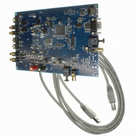
CDB4265
Description
BOARD EVAL FOR CS4265 CODEC
Manufacturer
Cirrus Logic Inc
Specifications of CDB4265
Main Purpose
Audio, CODEC
Embedded
No
Utilized Ic / Part
CS4265
Primary Attributes
Stereo, 24-Bit, 192 kHz Sample Rate
Secondary Attributes
Graphic User Interface, S/PDIF/ I2S / I2C / SPI Interface
Description/function
Audio CODECs
Operating Supply Voltage
5 V
Product
Audio Modules
For Use With/related Products
CS4265
Lead Free Status / RoHS Status
Contains lead / RoHS non-compliant
Lead Free Status / RoHS Status
Lead free / RoHS Compliant, Contains lead / RoHS non-compliant
Other names
598-1001


CS4265
Figure 42.Consumer Output Circuit (VD = 5 V) ........................................................................................ 51
Figure 43.TTL/CMOS Output Circuit ......................................................................................................... 51
Figure 44.Channel Status Data Buffer Structure ....................................................................................... 52
Figure 45.Flowchart for Writing the E Buffer ............................................................................................. 53
LIST OF TABLES
Table 1. Speed Modes .............................................................................................................................. 24
Table 2. Common Clock Frequencies ....................................................................................................... 24
Table 3. Slave Mode Serial Bit Clock Ratios ............................................................................................. 25
Table 4. Device Revision .......................................................................................................................... 35
Table 5. Freeze-able Bits .......................................................................................................................... 35
Table 6. DAC Digital Interface Formats .................................................................................................... 36
Table 7. De-Emphasis Control .................................................................................................................. 37
Table 8. Functional Mode Selection .......................................................................................................... 37
Table 9. ADC Digital Interface Formats .................................................................................................... 38
Table 10. MCLK Frequency ...................................................................................................................... 38
Table 11. DAC SDIN Source Selection ..................................................................................................... 39
Table 12. Example Gain and Attenuation Settings ................................................................................... 39
Table 13. PGA Soft Cross or Zero Cross Mode Selection ........................................................................ 40
Table 14. Analog Input Selection .............................................................................................................. 40
Table 15. Digital Volume Control Example Settings ................................................................................. 41
Table 16. DAC Soft Cross or Zero Cross Mode Selection ........................................................................ 42
Table 17. Transmitter Digital Interface Formats ........................................................................................ 44
6
DS657F2
Related parts for CDB4265
Image
Part Number
Description
Manufacturer
Datasheet
Request
R

Part Number:
Description:
Development Kit
Manufacturer:
Cirrus Logic Inc
Datasheet:
Part Number:
Description:
Development Kit
Manufacturer:
Cirrus Logic Inc
Datasheet:


Part Number:
Description:
High-efficiency PFC + Fluorescent Lamp Driver Reference Design
Manufacturer:
Cirrus Logic Inc
Datasheet:
Part Number:
Description:
Development Kit
Manufacturer:
Cirrus Logic Inc
Datasheet:
Part Number:
Description:
Development Kit
Manufacturer:
Cirrus Logic Inc
Datasheet:

Part Number:
Description:
Development Kit
Manufacturer:
Cirrus Logic Inc
Datasheet:
Part Number:
Description:
Development Kit
Manufacturer:
Cirrus Logic Inc
Datasheet:
Part Number:
Description:
Development Kit
Manufacturer:
Cirrus Logic Inc
Datasheet:
Part Number:
Description:
Development Kit
Manufacturer:
Cirrus Logic Inc
Datasheet:

Part Number:
Description:
EVALUATION BOARD FOR CS8427
Manufacturer:
Cirrus Logic Inc
Datasheet:

Part Number:
Description:
BOARD EVAL FOR CS8416 RCVR
Manufacturer:
Cirrus Logic Inc
Datasheet:

Part Number:
Description:
EVALUATION BOARD FOR CS8420
Manufacturer:
Cirrus Logic Inc
Datasheet:

Part Number:
Description:
KIT DEVELOPMENT EP9315 ARM9
Manufacturer:
Cirrus Logic Inc
Datasheet:

Part Number:
Description:
KIT DEVELOPMENT EP9302 ARM9
Manufacturer:
Cirrus Logic Inc
Datasheet: