CDB4265 Cirrus Logic Inc, CDB4265 Datasheet - Page 44
CDB4265
Manufacturer Part Number
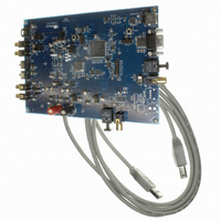
CDB4265
Description
BOARD EVAL FOR CS4265 CODEC
Manufacturer
Cirrus Logic Inc
Specifications of CDB4265
Main Purpose
Audio, CODEC
Embedded
No
Utilized Ic / Part
CS4265
Primary Attributes
Stereo, 24-Bit, 192 kHz Sample Rate
Secondary Attributes
Graphic User Interface, S/PDIF/ I2S / I2C / SPI Interface
Description/function
Audio CODECs
Operating Supply Voltage
5 V
Product
Audio Modules
For Use With/related Products
CS4265
Lead Free Status / RoHS Status
Contains lead / RoHS non-compliant
Lead Free Status / RoHS Status
Lead free / RoHS Compliant, Contains lead / RoHS non-compliant
Other names
598-1001


44
6.18
6.18.1 Transmitter Digital Interface Format (Bits 7:6)
6.18.2 Transmitter Output Driver Control (Bit 5)
6.18.3 Transmitter Mute Control (Bit 4)
6.18.4 Transmitted Validity Bit Control (Bit 3)
6.18.5 Transmitter Mono/Stereo Operation Control (Bit 2)
6.18.6 Mono Mode CS Data Source (Bit 1)
Tx_DIF1
7
Transmitter Control 2 - Address 12h
Tx_DIF1
Function:
The required relationship between LRCK, SCLK and SDIN for the transmitter is defined by the Transmitter
Digital Interface Format and the options are detailed in
Function:
When this bit is cleared, the transmitter output pin driver will be in the normal operational mode. When
set, the transmitter output pin driver will drive to a constant 0 V.
Function:
When this bit is cleared, the transmitter data will be in the normal operational mode. When set, the trans-
mitter will output all zero data.
Function:
This bit sets the transmitted Validity bit level.
When this bit is cleared, valid linear PCM audio data is indicated. When this bit is set, invalid or non-linear
PCM audio data is indicated.
Function:
When this bit is cleared, the transmitter will operate in stereo mode. When set, the transmitter will operate
in Mono Mode with one input channel’s data output in both A and B subframes (see
Status (C) Bit Management” on page
Function:
When this bit is cleared, the transmitter will transmit the channel A CS data in the A subframe and the
channel B CS data in the B subframe.
When this bit is set, the transmitter will transmit the CS data defined for the channel selected by the
MMTLR bit in both the A and B subframes.
0
0
1
1
Tx_DIF0
6
Tx_DIF0
0
1
0
1
TxOff
Table 17. Transmitter Digital Interface Formats
5
Left Justified, up to 24-bit data (default)
Right-Justified, 16-bit Data
Right-Justified, 24-bit Data
I²S, up to 24-bit data
TxMute
52) and the CS data defined by the MMTCS bit (see Section 6.18.6).
Description
4
V
3
Table 17
and
MMT
2
Figures
Format
0
1
2
3
5-7.
MMTCS
“IEC60958-3 Channel
1
Figure
5
6
7
7
CS4265
MMTLR
DS657F2
0
Related parts for CDB4265
Image
Part Number
Description
Manufacturer
Datasheet
Request
R

Part Number:
Description:
Development Kit
Manufacturer:
Cirrus Logic Inc
Datasheet:
Part Number:
Description:
Development Kit
Manufacturer:
Cirrus Logic Inc
Datasheet:


Part Number:
Description:
High-efficiency PFC + Fluorescent Lamp Driver Reference Design
Manufacturer:
Cirrus Logic Inc
Datasheet:
Part Number:
Description:
Development Kit
Manufacturer:
Cirrus Logic Inc
Datasheet:
Part Number:
Description:
Development Kit
Manufacturer:
Cirrus Logic Inc
Datasheet:

Part Number:
Description:
Development Kit
Manufacturer:
Cirrus Logic Inc
Datasheet:
Part Number:
Description:
Development Kit
Manufacturer:
Cirrus Logic Inc
Datasheet:
Part Number:
Description:
Development Kit
Manufacturer:
Cirrus Logic Inc
Datasheet:
Part Number:
Description:
Development Kit
Manufacturer:
Cirrus Logic Inc
Datasheet:

Part Number:
Description:
EVALUATION BOARD FOR CS8427
Manufacturer:
Cirrus Logic Inc
Datasheet:

Part Number:
Description:
BOARD EVAL FOR CS8416 RCVR
Manufacturer:
Cirrus Logic Inc
Datasheet:

Part Number:
Description:
EVALUATION BOARD FOR CS8420
Manufacturer:
Cirrus Logic Inc
Datasheet:

Part Number:
Description:
KIT DEVELOPMENT EP9315 ARM9
Manufacturer:
Cirrus Logic Inc
Datasheet:

Part Number:
Description:
KIT DEVELOPMENT EP9302 ARM9
Manufacturer:
Cirrus Logic Inc
Datasheet: