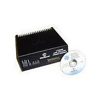
DM300022 Microchip Technology, DM300022 Datasheet - Page 34

DM300022
Manufacturer Part Number
DM300022
Description
MODULE PWR DSPICDEM MC1L LV 3PHS
Manufacturer
Microchip Technology
Specifications of DM300022
Main Purpose
Power Management, Motor Control
Embedded
Yes, MCU, 16-Bit
Utilized Ic / Part
dsPIC33FJxxxMC
Primary Attributes
3-Phase Low Voltage Power Module
Secondary Attributes
Motion Sensor Inputs: Hall Sensors or Optical Encoder
Silicon Manufacturer
Microchip
Silicon Core Number
DsPICDEM MC1L
Kit Application Type
Power Management - Motor Control
Application Sub Type
3 Phase Motor
Silicon Family Name
Piccolo
Rohs Compliant
Yes
Lead Free Status / RoHS Status
Lead free / RoHS Compliant
dsPICDEM™ MC1L 3-Phase Low Voltage Power Module
DS70097A-page 28
TABLE 1-6:
• Two different gain settings for the inverter leg shunt and DC bus shunt feedback
• The Scaling and trip levels for the inverter leg shunt signals are shown in
TABLE 1-7:
• The scaling and the trip levels for the bus shunt signal is given in Table 1-8:
TABLE 1-8:
• Changing the Hall Sensors scaling is accomplished via solderable links (e.g., LK1,
are implemented via LK5-12. These are located directly under the "Danger High
Voltage" label on the PCB. The user should consult Sheet 3 of the Schematics in
Appendix A to establish which links correspond to which signal. Note that links
must be changed in pairs (e.g., LK5 and LK6 together or LK7 and LK8 together,
etc.) for correct operation (see below).
Table 1-7:
Note: The shaded setting should not be used, as it will not adequately protect the
LK2 and LK3 for U1). These are located adjacent to the transducers. The links
change the number of turns that pass through the transducer over a 3:1 range.
Tinned copper wire of a suitable current rating should be used. Only one link at a
time should be used or unpredictable current scaling will occur. The user
should ensure that the maximum length of lead protruding below the PCB is 4 mm
for voltage clearance reasons. The scaling and corresponding trip levels are
shown in Table 1-9 where the links referred to are for U2.
Trip Level (A)
Scaling (A/V)
power devices from thermal overload.
Trip Level (A)
Scaling (A/V)
LK 4 Setting
SHUNT FEEDBACK POLARITY SELECTION
INVERTER LEG SHUNT SCALING SELECTION
BUS SHUNT SCALING SELECTION
1-2
2-3
Bipolar
±10.9
5.45
Links Open
Links Open
±10.8
5.39
Unipolar
5.45
24.5
Feedback Range
Unipolar
© 2003 Microchip Technology Inc.
Bipolar
Bipolar
±24.0
12.0
Links Shorted
Links Closed
±23.9
11.9
Unipolar
12.0
54.0


