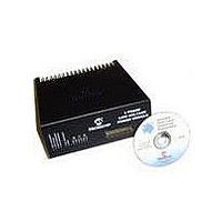
DM300022 Microchip Technology, DM300022 Datasheet - Page 25

DM300022
Manufacturer Part Number
DM300022
Description
MODULE PWR DSPICDEM MC1L LV 3PHS
Manufacturer
Microchip Technology
Specifications of DM300022
Main Purpose
Power Management, Motor Control
Embedded
Yes, MCU, 16-Bit
Utilized Ic / Part
dsPIC33FJxxxMC
Primary Attributes
3-Phase Low Voltage Power Module
Secondary Attributes
Motion Sensor Inputs: Hall Sensors or Optical Encoder
Silicon Manufacturer
Microchip
Silicon Core Number
DsPICDEM MC1L
Kit Application Type
Power Management - Motor Control
Application Sub Type
3 Phase Motor
Silicon Family Name
Piccolo
Rohs Compliant
Yes
Lead Free Status / RoHS Status
Lead free / RoHS Compliant
© 2003 Microchip Technology Inc.
• R60, R62, R67, Q12, C24, C28 – These components act to provide a dynamic
• Brake Resistor – A 50W metal clad 75W resistor mounted to the heat sink is
1.5.5
In order to provide isolated current feedback, Hall effect closed loop DC current
transducers (LEM LTS 15-NP) devices have been installed. These devices have the
following characteristics:
• Single 5V supply with 2.5V (nominal) representing 0A
• Bipolar current sensing with ±48A given by 4.5V and 0.5V respectively with a
• >200 kHz bandwidth
• 3 kV AC isolation
A detailed device data sheet can be obtained from www.lem.com.
Two such devices (U3 and U4) are installed in series with the output connections of
phases R and Y. These are configured to have 2 turns through the device with LK 14
and 17 installed. This gives a maximum sensed current of ±24A and a gain of 12A/V.
Note that a third device is not required, as the sum of the output line currents must
always be zero due to symmetry. The one exception to this is during a FAULT
condition that is detected elsewhere.
The third device (U2) is on the positive DC input of wire of the input power stage (see
Figure 1-1). This device is configured to have 2 turns through it as delivered with LK2
installed. This gives a maximum sensed current of 24A and a gain of 12A/V. U2 is
used to provide input over current protection, as well as feedback of the DC input
current.
level shifting circuit to U23 while Q10 switches. Inductance of the power tracking
between the source of Q10 due to the physical board layout means there is a
substantial transient voltage (up to 2V in this case) between the +15V supply star
point reference and the source of Q10. This simple low cost circuit allows the
power supply of U23 to move transiently. Q12 provides a level shift to ensure
correct assertion of the firing command. In applications with fewer constraints on
physical layout and/or lower switching speed requirements, these components
may not be needed.
connected to pads J7 and J8. The value of the resistor has been chosen to allow
a maximum dissipation of 45W. If the user wishes to be able to dissipate more
power, then an external resistor can be connected to pins 6 and 7 of the 7-pin
output connector. This will operate in parallel with the internal resistor. If the user
wishes to change the value of the internal resistor or disconnect it, they should
read Section 1.6.3.2 “Modifying or Removing the Internal Braking Resistor”.
single turn through the transducer.
Isolated Current Feedback (Appendix A Sheets 1 and 2)
Set Up and Operation
DS70097A-page 19


