DM300022 Microchip Technology, DM300022 Datasheet - Page 16
DM300022
Manufacturer Part Number
DM300022
Description
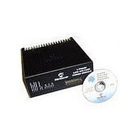
MODULE PWR DSPICDEM MC1L LV 3PHS
Manufacturer
Microchip Technology
Specifications of DM300022
Main Purpose
Power Management, Motor Control
Embedded
Yes, MCU, 16-Bit
Utilized Ic / Part
dsPIC33FJxxxMC
Primary Attributes
3-Phase Low Voltage Power Module
Secondary Attributes
Motion Sensor Inputs: Hall Sensors or Optical Encoder
Silicon Manufacturer
Microchip
Silicon Core Number
DsPICDEM MC1L
Kit Application Type
Power Management - Motor Control
Application Sub Type
3 Phase Motor
Silicon Family Name
Piccolo
Rohs Compliant
Yes
Lead Free Status / RoHS Status
Lead free / RoHS Compliant


dsPICDEM™ MC1L 3-Phase Low Voltage Power Module
DS70097A-page 10
1.2.4
The user should ensure that the following sequence, are followed.
1.2.4.1
• With the control card plugged in, turn on the power supply feeding the control PCB
• One or more of the fault lights may illuminate. This is normal.
• Turn on the DC supply to the power module.
• Reset the system by activating the active high ISO_RESET line. The
1.2.4.2
• Stop firing all power devices.
• Turn off the incoming DC supply.
• Wait until the red DC bus LED indicator visible through the ventilation holes in the
• Turn off the power supply feeding the control card (if required).
1.2.5
The Brake chopper switch has been designed so that it may be modulated up to
a maximum frequency of 16 kHz. This frequency limit is chosen for power dissipa-
tion and low voltage power supply consumption reasons. In most braking applications,
a lower modulation frequency will be used, as there is little benefit (apart from acoustic
noise) from modulating at such a high frequency.
The six inverter switches have been designed so that they may be modulated up
to a maximum frequency of 20 kHz. This frequency limit is chosen for power
dissipation and low voltage power supply consumption reasons. Unless extremely low
output current harmonics or very high bandwidth control is required, it is suggested
that a 16 kHz modulation frequency be used. This offers lower loss while still being
inaudible. It also has the advantage that the "dead time" will cause less distortion of
the output voltage.
Given the high side and low side switches of the inverter are connected in series
across the DC bus (see Figure 1-2), both switches should never be turned on at the
same time. Turning both switches on effectively places a short circuit across the DC
bus and is called "shoot-through". Shoot-through should be avoided at all costs. In
order to avoid shoot-through, an appropriate time delay must be inserted between the
turn off command to one device and the turn on command to the other device of the
same inverter leg. This time is called the "dead time". The required dead time
depends on the switching speeds of the power devices and the timing delays due to
the optocouplers and the gate drive circuits. No hardware dead time is included in the
design as it is included as a feature of the Motor Control PWM module of the dsPIC
device. A minimum dead time of 2 µs should be used. This applies to both turn on
and turn off of both devices. Writing to the appropriate registers in the dsPIC
(DTCON1 and DTCON2) sets the dead time. Refer to the dsPIC30F Family
Reference Manual (DS70046) for details.
(if not already on).
ISO_RESET line is on pin 33 of the 37-pin, D-type (see Section 1.8 “User Sig-
nal Connector Pinout (37-Pin, D-Type)”). On the dsPICDEM MC1 Motor
Control Development Board, this signal is routed to pin 14 of the 30F6010 dsPIC
device, which is on Port RE9. The minimum pulse width for the reset is 2 µs. The
RESET should be done in coordination with the SPI™ handling routine of the
dsPIC device to ensure correct synchronization of the serial interface providing
the isolated voltage feedback (see Section 1.5.7.2 “Isolated Voltage Feed-
back”). The system is now ready to use.
top of the unit has gone out. (This will take 5 minutes or less.)
Power-Up/Power-Down Sequence
POWER-UP SEQUENCE
POWER-DOWN SEQUENCE
Modulating The Power Devices
© 2003 Microchip Technology Inc.
Related parts for DM300022
Image
Part Number
Description
Manufacturer
Datasheet
Request
R

Part Number:
Description:
Manufacturer:
Microchip Technology Inc.
Datasheet:
Part Number:
Description:
Manufacturer:
Microchip Technology Inc.
Datasheet:
Part Number:
Description:
Manufacturer:
Microchip Technology Inc.
Datasheet:
Part Number:
Description:
Manufacturer:
Microchip Technology Inc.
Datasheet:
Part Number:
Description:
Manufacturer:
Microchip Technology Inc.
Datasheet:
Part Number:
Description:
Manufacturer:
Microchip Technology Inc.
Datasheet:
Part Number:
Description:
Manufacturer:
Microchip Technology Inc.
Datasheet:
Part Number:
Description:
Manufacturer:
Microchip Technology Inc.
Datasheet: