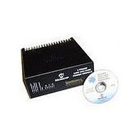
DM300022 Microchip Technology, DM300022 Datasheet - Page 19

DM300022
Manufacturer Part Number
DM300022
Description
MODULE PWR DSPICDEM MC1L LV 3PHS
Manufacturer
Microchip Technology
Specifications of DM300022
Main Purpose
Power Management, Motor Control
Embedded
Yes, MCU, 16-Bit
Utilized Ic / Part
dsPIC33FJxxxMC
Primary Attributes
3-Phase Low Voltage Power Module
Secondary Attributes
Motion Sensor Inputs: Hall Sensors or Optical Encoder
Silicon Manufacturer
Microchip
Silicon Core Number
DsPICDEM MC1L
Kit Application Type
Power Management - Motor Control
Application Sub Type
3 Phase Motor
Silicon Family Name
Piccolo
Rohs Compliant
Yes
Lead Free Status / RoHS Status
Lead free / RoHS Compliant
© 2003 Microchip Technology Inc.
1.2.7
The following FAULT protection is provided which automatically disables all firing
independent of firing commands.
TABLE 1-4:
Reset of a FAULT is done by asserting the ISO_RESET line of the 37-pin connector.
This should be done for a minimum time of 2 µs. The RESET must be carried out in
coordination with the SPI handling routine of the dsPIC device to ensure correct
synchronization of the serial interface providing the isolated voltage feedback (see
Section 1.5.7.2 “Isolated Voltage Feedback”).
Note that the fault levels are set to represent abnormal operation. Operation of the
system just beneath the trip levels may be beyond the thermal capability of the
system. See Section 1.4 “Current and Power Limitations” for details.
1.2.8
As far as the inverter power devices are concerned, it is the instantaneous tempera-
tures of their junctions that matter for correct operation and reliability. As the current
that flows through a particular power device changes through an electrical cycle, so
does the loss. At high fundamental output frequencies (e.g., 60 Hz), the devices have
sufficient thermal "mass" to smooth out much of the effect of the variation in loss, so
that the peak device junction is due to the (much lower) average dissipation. As the
output frequency reduces, the peak device junction temperature reaches the worst
case loss.
It is common practice to include a stall detection algorithm in software. This is
designed to not only protect the power components, but also the motor from thermal
overload. As it is impractical to include stall detection in hardware that maintains
flexibility for development but still provides 100% protection, it is assumed that the
software in the dsPIC device provides this feature. The algorithm should monitor rotor
speed and cause a system trip if the rotor speed is at or near zero for greater than an
appropriate length of time while the inverter is energized. A stall trip time of 2 seconds
is suggested.
R, Y, B Bottom Switch Current
DC Bus Current
DC Bus Voltage
Brake Switch Current
Heat sink Over Temperature
Isolated DC Input Current Feedback
R, Y Isolated Phase Current Feedback
* If a large rate of change of current occurs due to the use of a load with low
inductance, then the voltage across the self-inductance of the shunts will cause
trips to occur at a lower level than that stated.
Note: If SHUNT OVERCURRENT trips are occurring, but not HALL
FAULT Protection
Operation at Low Output Frequencies and Stall
OVERCURRENT trips, this may indicate that an inverter shoot-through is
occurring. The user should immediately remove AC power from the system
and check that the correct 2 µs dead time exists on the inverter firing signals
using an oscilloscope.
FAULT PROTECTION
Fault Source
Set Up and Operation
Nominal Trip
65°C (150F)
±24.0A*
±23.9A*
+24.5A
+22.2A
±22.2A
58.7V
Level
Shunt Overcurrent
Brake Overcurrent
Over Temperature
Hall Overcurrent
LED Indicator
Over Voltage
DS70097A-page 13


