DM300022 Microchip Technology, DM300022 Datasheet - Page 32

DM300022
Manufacturer Part Number
DM300022
Description
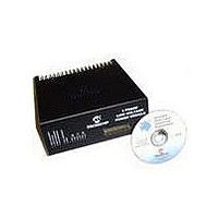
MODULE PWR DSPICDEM MC1L LV 3PHS
Manufacturer
Microchip Technology
Specifications of DM300022
Main Purpose
Power Management, Motor Control
Embedded
Yes, MCU, 16-Bit
Utilized Ic / Part
dsPIC33FJxxxMC
Primary Attributes
3-Phase Low Voltage Power Module
Secondary Attributes
Motion Sensor Inputs: Hall Sensors or Optical Encoder
Silicon Manufacturer
Microchip
Silicon Core Number
DsPICDEM MC1L
Kit Application Type
Power Management - Motor Control
Application Sub Type
3 Phase Motor
Silicon Family Name
Piccolo
Rohs Compliant
Yes
Lead Free Status / RoHS Status
Lead free / RoHS Compliant
dsPICDEM™ MC1L 3-Phase Low Voltage Power Module
DS70097A-page 26
1.5.9.2
The feedback signals from the inverter leg shunts and the bus current signal derived
from them (see Section 1.5.6.2 “Inverter Leg Shunt Resistor Feedback” and
Section 1.5.6.3 “DC Bus Shunt Resistor Feedback” ), are used to detect over
current trips. Note that the shunts will see "shoot-through" events which bypass the
Hall current sensors. The circuitry used to implement this is described below:
• U25 – A quad package comparator used for the over current threshold compari-
• U27-B – A remaining op amp package used to generate the HIGH_REF (+4.5V)
• U26 (A and B) – Two, two-input NAND gates configured as a SET dominant SR
• D5, R202 – An LED and its associated current limiting resistor for the visual
1.5.9.3
The feedback signal derived for the DC bus voltage (see Section 1.5.7 “Voltage
Feedback (Appendix A Sheets 1, 6 and 7)” is used to detect an over-voltage condi-
tion. The threshold is set at approximately 59V in order to protect the power devices
and the DC bus capacitors. A similar circuit as described in Section 1.5.9.2 “Inverter
Shunt Over-current” is used.
1.5.9.4
The feedback signal derived from the brake chopper shunt is used to detect an
over-current. The threshold is set at 24.5 A. The circuitry used to implement the trip is
similar to that described in Section 1.5.9.2 “Inverter Shunt Over-current”.
1.5.9.5
To protect the power devices from thermal overload, a heat sink temperature trip is
included. The trip temperature is set at nominal value of 65°C (150F). The circuitry
used to implement this is described below:
• U1 – A Microchip TC622EAT temperature trip IC. This IC only requires an external
• R116 and C42 – These filter the output of U1 to prevent false tripping due to
• Latching and indication is identical to that described in Section 1.5.9.2 “Inverter
sons. Each comparator has a small amount of hysteresis (formed by R119 and
R120 for example) to ensure no output chattering occurs. Note that the inverter
leg shunts are compared for positive current, which is when the current is flowing
in a switch. The bus shunt is compared for a negative value to protect against
faults during braking/generating. R109 forms the pull-up for the open collector
outputs of U25. A small amount of filtering is used (e.g., R118, C45) to prevent
spikes on the shunt signals causing false trips.
from the Microchip MCP1525 2v5 reference.
flip-flop. The SET dominance is important to ensure correct fault action even if the
RESET input is active.
indication of the FAULT.
resistor (R34) to set the nominal trip temperature. As the version chosen is pack-
aged in a TO220, this is easily mounted along with the other power devices to the
heat sink. This ensures excellent thermal coupling. As the tab of the device is not
isolated, a thermally conductive insulator is used.
noise.
Shunt Over-current”.
INVERTER SHUNT OVER-CURRENT
DC BUS OVER-VOLTAGE
BRAKE OVER-CURRENT
HEAT SINK OVER-TEMPERATURE
© 2003 Microchip Technology Inc.


