MCP3909RD-3PH1 Microchip Technology, MCP3909RD-3PH1 Datasheet - Page 67
MCP3909RD-3PH1
Manufacturer Part Number
MCP3909RD-3PH1
Description
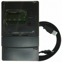
REF DESIGN MCP3909 3PH ENGY MTR
Manufacturer
Microchip Technology
Datasheets
1.MCP3909T-ISS.pdf
(44 pages)
2.MCP3909T-ISS.pdf
(104 pages)
3.MCP3909RD-3PH3.pdf
(88 pages)
Specifications of MCP3909RD-3PH1
Main Purpose
Power Management, Energy/Power Meter
Embedded
No
Utilized Ic / Part
MCP3909, PIC18F2520, PIC18F4550
Primary Attributes
3-Ph, 220 VAC, In Case, LCD, USB, GUI
Secondary Attributes
Opto-Isolated Interface for Safety
Operating Voltage
220 V
Operating Current
5 A
Description/function
Energy Meter
For Use With/related Products
MCP3909
Lead Free Status / RoHS Status
Not applicable / Not applicable


© 2008 Microchip Technology Inc.
6.8.4
The final calibration step will be to calibrate the RMS current offset of the meter, if
desired. The default value for this calibration step is 10% of the ICAL current that was
used for steps 1 and 2. The user can enter the exact value at this point in the dialog
box for more accurate meter calibration.
FIGURE 6-6:
minimum current for active power offset calibration (in Amperes).
Section 5.3.11 describes the registers and equations that the software uses at this
point to calibrate the RMS offset correction of the meter for the appropriate phase. Note
that the software does not calculate the RMS voltage offset.
After the completion of step 4, the software will prompt you to save the calibration
registers to EEPROM.
Calibration of this phase is now complete.
6.8.5
The line cycle pull drop down box allows the user to change the number of line cycles
being used to accumulate the energy during calibration. After this occurs, the software
automatically performs a write to the LINE_CYC register.
3-Phase Energy Meter Calibration Software
Calibration Step 4 - Configuration C4
Calibration Line Cycle Selection Pull Down
Calibration Step C4 with calibration settings input boxes for the
DS51643B-page 63
Related parts for MCP3909RD-3PH1
Image
Part Number
Description
Manufacturer
Datasheet
Request
R

Part Number:
Description:
BOARD DES MCP3909 ENERGY METER
Manufacturer:
Microchip Technology
Datasheet:

Part Number:
Description:
REF DESIGN FOR MCP3909 W/18F2520
Manufacturer:
Microchip Technology
Datasheet:

Part Number:
Description:
Manufacturer:
Microchip Technology Inc.
Datasheet:
Part Number:
Description:
Manufacturer:
Microchip Technology Inc.
Datasheet:
Part Number:
Description:
Manufacturer:
Microchip Technology Inc.
Datasheet:
Part Number:
Description:
Manufacturer:
Microchip Technology Inc.
Datasheet:
Part Number:
Description:
Manufacturer:
Microchip Technology Inc.
Datasheet:
Part Number:
Description:
Manufacturer:
Microchip Technology Inc.
Datasheet:
Part Number:
Description:
Manufacturer:
Microchip Technology Inc.
Datasheet:
Part Number:
Description:
Manufacturer:
Microchip Technology Inc.
Datasheet: