MCP3909RD-3PH1 Microchip Technology, MCP3909RD-3PH1 Datasheet - Page 13
MCP3909RD-3PH1
Manufacturer Part Number
MCP3909RD-3PH1
Description
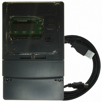
REF DESIGN MCP3909 3PH ENGY MTR
Manufacturer
Microchip Technology
Datasheets
1.MCP3909T-ISS.pdf
(44 pages)
2.MCP3909T-ISS.pdf
(104 pages)
3.MCP3909RD-3PH3.pdf
(88 pages)
Specifications of MCP3909RD-3PH1
Main Purpose
Power Management, Energy/Power Meter
Embedded
No
Utilized Ic / Part
MCP3909, PIC18F2520, PIC18F4550
Primary Attributes
3-Ph, 220 VAC, In Case, LCD, USB, GUI
Secondary Attributes
Opto-Isolated Interface for Safety
Operating Voltage
220 V
Operating Current
5 A
Description/function
Energy Meter
For Use With/related Products
MCP3909
Lead Free Status / RoHS Status
Not applicable / Not applicable


1.3
© 2008 Microchip Technology Inc.
GETTING STARTED
To describe how to use the MCP3909 3-Phase Energy Meter Reference Design, the
following example is given using both a 4-Wire 3-phase, 220VAC line voltage and
connections using an energy meter calibrator equipment or other programmable load
source. The meter design uses a 5A load for calibration current and a maximum current
(I
All connections described in this section are dependent on the choice of current
sensing element and a secondary external transformer may be required in higher
current meter designs.
For testing a calibrated meter, the following connections apply for a 4-wire connection.
1.3.1
FIGURE 1-3:
1.3.2
The meter will turn on when the line connection has 220V connected to any of the three
phases.
1.3.3
After connecting the USB cable to a computer running Windows
meter should be recognized as a HID (Human Interface Device) compliant USB device.
FIGURE 1-4:
MAX
) of 10A.
Step 1: Wiring for 4-Wire Line and Load connections
Step 2: Turn On Line/Load Power to the Meter (Power the
Meter).
Step 3: Connect isolated USB Interface Module.
Line
Phase A
Example Connections using a 4-Wire System.
USB Interface Connections
Load
Line
Phase B
Load
Product Overview
Line
Phase C
Load
®
operating system, the
Neutral
DS51643B-page 9
Related parts for MCP3909RD-3PH1
Image
Part Number
Description
Manufacturer
Datasheet
Request
R

Part Number:
Description:
BOARD DES MCP3909 ENERGY METER
Manufacturer:
Microchip Technology
Datasheet:

Part Number:
Description:
REF DESIGN FOR MCP3909 W/18F2520
Manufacturer:
Microchip Technology
Datasheet:

Part Number:
Description:
Manufacturer:
Microchip Technology Inc.
Datasheet:
Part Number:
Description:
Manufacturer:
Microchip Technology Inc.
Datasheet:
Part Number:
Description:
Manufacturer:
Microchip Technology Inc.
Datasheet:
Part Number:
Description:
Manufacturer:
Microchip Technology Inc.
Datasheet:
Part Number:
Description:
Manufacturer:
Microchip Technology Inc.
Datasheet:
Part Number:
Description:
Manufacturer:
Microchip Technology Inc.
Datasheet:
Part Number:
Description:
Manufacturer:
Microchip Technology Inc.
Datasheet:
Part Number:
Description:
Manufacturer:
Microchip Technology Inc.
Datasheet: