MCP3909RD-3PH1 Microchip Technology, MCP3909RD-3PH1 Datasheet
MCP3909RD-3PH1
Specifications of MCP3909RD-3PH1


Related parts for MCP3909RD-3PH1


MCP3909RD-3PH1 Summary of contents
Page 1
... Microchip Technology Inc. 3-Phase Energy Meter Reference Design Using the PIC18F2520 MCP3909 DS51643B ...
Page 2
... PowerMate, PowerTool, REAL ICE, rfLAB, Select Mode, Total Endurance, WiperLock and ZENA are trademarks of Microchip Technology Incorporated in the U.S.A. and other countries. SQTP is a service mark of Microchip Technology Incorporated in the U.S.A. All other trademarks mentioned herein are property of their respective companies. ...
Page 3
... PIC18F2520 Protocol ................................................................................... 37 Chapter 5. Meter Calibration 5.1 Calibration Overview .................................................................................... 39 5.2 Active Power Signal Flow and Calibration .................................................... 41 5.3 RMS Current, RMS Voltage, Apparent Power Signal Flow and Calibration . 42 © 2008 Microchip Technology Inc. MCP3909 3-PHASE ENERGY METER REFERENCE DESIGN Table of Contents DS51643B-page iii ...
Page 4
... A.11 USB Interface Module - Top Silk-Screen Layer ......................................... 76 A.12 USB Interface Module - Top Traces And Pads Layer ................................ 76 A.13 USB Interface Module - Bottom Silk-Screen Layer .................................... 77 A.14 USB Interface Module - Bottom Traces And Pads Layer .......................... 77 Appendix B. Bill Of Materials (BOM) Worldwide Sales and Service .....................................................................................84 DS51643B-page iv © 2008 Microchip Technology Inc. ...
Page 5
... Document Layout • Conventions Used in this Guide • Recommended Reading • The Microchip Web Site • Customer Support • Document Revision History © 2008 Microchip Technology Inc. MCP3909 3-PHASE ENERGY METER REFERENCE DESIGN Preface NOTICE TO CUSTOMERS ® IDE on-line help. ...
Page 6
... Appendix A. “Schematic and Layouts” – Shows the schematic and layout diagrams • Appendix B. “Bill Of Materials (BOM)” – Lists the parts used to build the DS51643B-page 2 © 2008 Microchip Technology Inc. ...
Page 7
... N‘Rnnnn Text in angle brackets < > Courier New font: Plain Courier New Italic Courier New Square brackets [ ] Curly brackets and pipe character Ellipses... © 2008 Microchip Technology Inc. Represents Referenced books MPLAB Emphasized text ...is the only compiler... A window the Output window A dialog ...
Page 8
... Customers should contact their distributor, representative or field application engineer (FAE) for support. Local sales offices are also available to help customers. A listing of sales offices and locations is included in the back of this document. Technical support is available through the web site at: http://support.microchip.com DS51643B-page 4 © 2008 Microchip Technology Inc. ...
Page 9
... Chasnged values of reistors in text and Figure 2-1. 4. Appendix A. “Schematic and Layouts”: Updated Schematics and Board Layouts for Revision 2. 5. Appendix B. “Bill Of Materials (BOM)”: Updated for Revision 2. Revision A (February 2007) • Initial Release of this Document. © 2008 Microchip Technology Inc. Preface DS51643B-page 5 ...
Page 10
... MCP3909 3-Phase Energy Meter Reference Design NOTES: DS51643B-page 6 © 2008 Microchip Technology Inc. ...
Page 11
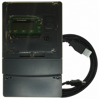
... PIC18F2520 can be used to create custom calibration setups. The energy meter software offers an automated step by step calibration process that can be used to quickly calibrate energy meters. FIGURE 1-1: © 2008 Microchip Technology Inc. MCP3909 3-PHASE ENERGY METER REFERENCE DESIGN MCP3909 3-Phase Energy Meter Reference Design. ...
Page 12
... MCP3909 Data Sheet, “Energy Metering IC with SPI Interface and Active Power Pulse Output” (DS22025) DS51643B-page 8 LCD DISPLAY USB PIC18F4550 PIC18F4550 USB Interface Module PIC18F2520 In-Circuit Programming MCP3909 V MCP3909 MCP3909 REG Main Board 3-Phase Meter Case Current T Transformers CT © 2008 Microchip Technology Inc. ...
Page 13
... Step 3: Connect isolated USB Interface Module. After connecting the USB cable to a computer running Windows meter should be recognized as a HID (Human Interface Device) compliant USB device. FIGURE 1-4: © 2008 Microchip Technology Inc. Phase B Phase A Load Line Load Example Connections using a 4-Wire System. ...
Page 14
... MCP3909 3-Phase Energy Meter Reference Design 1.3.4 Step 4: Run PC Calibration Software After the PC has recognized that the energy meter is connected, the calibration software will allow real-time testing and calibration of the meter. FIGURE 1-5: DS51643B-page 10 MCP3909 3-Phase Energy Meter Reference Design Software. © 2008 Microchip Technology Inc. ...
Page 15
... FB (Note) PHA-L J6:1 PHA-N J6:2 FIGURE 2-1: Analog Front End, Phase A Connections and Reference Designators shown. © 2008 Microchip Technology Inc. MCP3909 3-PHASE ENERGY METER REFERENCE DESIGN Chapter 2. Hardware , the channel 1 input signal size will be 718 mV RMS 1000:1 23.2Ω ...
Page 16
... ADCs FIGURE 2-2: Timing Structure of PIC18F2520 Interrupts and Calculations. DS51643B-page 12 39.3216 MHz 1.6384 MHz (50 Hz) 1.96606 MHz (60 Hz) R31 R34 MCLK input MCP3909 MCP3909 t SAMPLE IRQ t SAMPLE X1 PIC MCU CCP2 / 32768 Option 2 To PIC18F2520 IRQ DR Pulse DR © 2008 Microchip Technology Inc. ...
Page 17
... PC and the LCD on the USB interface module for output display Output Pulse RS-232 RX, TX 3-Phase Energy Meter Main Board FIGURE 2-3: Meter Output Diagram. © 2008 Microchip Technology Inc. and opto-isolator U . With the DC-DC Converter U17 ...
Page 18
... Power Supply Circuit. IEC62053 states that the meter must be able to operate from any single phase with 70% nominal voltage. DS51643B-page 14 Note ferrite beads. Ferrite beads have an impedance of the specified value at 100 MHz. 600 470 µF +5V 100 nF LM1117-5.0 100 nF © 2008 Microchip Technology Inc. ...
Page 19
... The calibration registers fall into one of three categories: offset, gain, and LSB, denoted by _OFF, _GAIN and _GLSB register names. In addition there are two registers, CFNUM and CFDEN, that calibrate the output pulse, CF. © 2008 Microchip Technology Inc. MCP3909 3-PHASE ENERGY METER REFERENCE DESIGN DS51643B-page 15 ...
Page 20
... These functions are not implemented with this version of the firmware/software release. FIGURE 3-1: PIC18F2520 Signal Flow (Phase A), not all registers shown. DS51643B-page 16 RMS Current Apparent Power Σ X PHA_I_RMS_OFF:16 Active Power Σ X PHA_W_GAIN:16 PHA_W_OFF: Meter Output (LCD or other) PHA_VA_GAIN:16 Σ X PHASES B & C Σ © 2008 Microchip Technology Inc. ...
Page 21
... PHC_W_RAW 0x076 PHA_W 0x07A PHB_W 0x07E PHC_W 0x082 PHA_VA_RAW 0x088 PHB_VA_RAW 0x08E PHC_VA_RAW © 2008 Microchip Technology Inc. R/W 16 R/W Configuration register for operating mode of the meter 16 — Reserved 16 R Status Register 16 — Reserved 16 R/W Configuration register for calibration control ...
Page 22
... R/W Phase B delay time shifted) (delay between voltage and current, voltage is 8 R/W Phase C delay time shifted) 8 — Reserved 16 R/W Offset adjustment for phase A RMS current reading 16 R/W Offset adjustment for phase A RMS voltage reading Description © 2008 Microchip Technology Inc. ...
Page 23
... PHC_VAR_GLSB 0x1A0 ENERGY_W_GLSB 0x1A2 ENERGY_VA_GLSB 0x1A4 ENERGY_VAR_GLSB 0x1A6 CREEP_THRESH © 2008 Microchip Technology Inc. R/W 16 R/W Offset adjustment for phase B RMS current reading 16 R/W Offset adjustment for phase B RMS voltage reading 16 R/W Offset adjustment for phase C RMS current reading 16 R/W Offset adjustment for phase C RMS voltage reading ...
Page 24
... R/W CF Calibration Pulse correction factor 16 R/W Power Up Configuration Register 16 R/W Status of Phase A Calibration 16 R/W Status of Phase B Calibration 16 R/W Status of Phase C Calibration 48 R/W Standard Phase Active Power Reading used during calibration for gain matching) Description (place holder register © 2008 Microchip Technology Inc. ...
Page 25
... Both negative and positive energy accumulated (negative energy is subtracted) bit 1 Phase: The Phase Bit 1 = Single Point Phase Correction 0 = Multi-Point Phase Correction (future) bit 0 CREEP: No-Load Threshold Bit 1 = Enabled 0 = Disabled © 2008 Microchip Technology Inc. MODE1 Register Bits Address Cof 0x000 16 R/W R/W ...
Page 26
... This is the sign bit of raw active power before absolute value taken This is the sign bit of raw active power before absolute value taken This is the sign bit of raw active power before absolute value taken U-0 U-0 — — — bit PHB_S PHC_S bit Bit is unknown © 2008 Microchip Technology Inc. ...
Page 27
... LINE_CYC line cycles. At that point, all registers will be updated, and no further updates will be done until this bit is set again or CAL_MODE bit is cleared bit 0 CAL_MODE: Calibration Mode Bit This bit enables calibration mode Calibration Mode Enabled 0 = Calibration Mode Disabled © 2008 Microchip Technology Inc. Register CAL_CONTROL Bits Address Cof 0x008 ...
Page 28
... LINE_CYC_CNT REGISTER Bits Address Cof 16 0x00C R (LINE_CYC) PHY_I_RMS_RAW2 REGISTERS Bits Address Cof 48 0x010 R 48 0x024 R 48 0x038 R PHY_I_RMS_RAW REGISTERS Bits Address Cof 16 0x016 R 16 0x02A R 16 0x03E line cycle setting and then re-starts at 0, where © 2008 Microchip Technology Inc. ...
Page 29
... LSB resolution of 0.1V, is specific for the 5(10)A, 220V rating that this meter is designed for). These registers are overwritten every LINE_CYC line cycles (written only once if calibration is enabled). © 2008 Microchip Technology Inc. PHY_I_RMS REGISTERS Bits ...
Page 30
... LINE_CYC line cycles (written only once if calibration is enabled). DS51643B-page 26 I_RMS REGISTER Bits Address Cof 24 0x04C R PHY_W_RAW REGISTERS Bits Address Cof 48 0x064 R 48 0x06A R 48 0x070 R PHY_W REGISTERS Bits Address Cof 32 0x076 R 32 0x07A R 32 0x07E R © 2008 Microchip Technology Inc. ...
Page 31
... This is the raw phase y reactive power. This is the register to be read during calibration for calculating the gain values associated with reactive phase y power, PHy_VAR_GAIN and PHy_VAR_GLSB. This register is overwritten every LINE_CYC line cycles (written only once if calibration is enabled). NOT IMPLEMENTED IN THIS FIRMWARE/SOFTWARE RELEASE. © 2008 Microchip Technology Inc. PHY_VA_RAW REGISTERS Bits Address Cof ...
Page 32
... LINE_CYC line cycles. Each LSB represents 1.6 us with a 40 MHz clock on the microcontroller. This register is overwritten every LINE_CYC line cycles (written only once if calibration is enabled). DS51643B-page 28 PHY_VAR REGISTERS Bits Address Cof 32 0x0B2 R 32 0x0B6 R 32 0x0BA R PERIOD REGISTER Bits Address Cof 32 0x0C0 R © 2008 Microchip Technology Inc. ...
Page 33
... PHy_W_GAIN values are all set to their default value of 0x4000 (16,384). The ENERGY_W_L_RAW register is the register that should be read when calibrating CFNUM and CFDEN. This register is updated every line cycle (updating ends once LINE_CYC line cycles have passed if calibration is enabled). © 2008 Microchip Technology Inc. ENERGY_W_ REGISTERS Bits Address 64 ...
Page 34
... PHC_VA_GAIN • ) -------------------------------------- - PHC_V_RMS_RAW ⎝ 32768 the period (in 1.6 µs clock ticks) for the most recent LINE_CYC line cycles. ⎛ ⎞ PHA_VA_GAIN • ) -------------------------------------- - ⎝ ⎠ 32768 ⎞ ⎠ • ⎞ PERIOD 128 • ------------------------------------- - ⎠ 65536 © 2008 Microchip Technology Inc. ...
Page 35
... ENERGY_VAR (NOT IMPLEMENTED) REGISTER 3-24: Name ENERGY_VAR ENERGY_VAR_Z ENERGY_VAR_L ENERGY_VAR_L_RAW NOT IMPLEMENTED IN THIS FIRMWARE/SOFTWARE RELEASE. © 2008 Microchip Technology Inc. PHY_I_ABS_MAX REGISTER Bit Address Cof 8 0x0F8 R 8 0x0FA R ...
Page 36
... NOT IMPLEMENTED IN THIS FIRMWARE/SOFTWARE RELEASE. DS51643B-page 32 PHY_DELAY REGISTER Bit Address Cof 8 0x140 R/W 8 0x141 R/W 8 0x142 R/W PHY_I_RMS_OFF REGISTER Bit Address Cof 16 0x144 R/W 16 0x148 R/W 16 0x14A R/W PHY_V_RMS_OFF REGISTER Bit Address Cof 16 0x146 R/W 16 0x14A R/W 16 0x14E R/W © 2008 Microchip Technology Inc. ...
Page 37
... Phase y active power gain so that all results can be calibrated to produce equal CF pulses/watt-hour. The signed 16-bit number produces a change in the PHy_W_RAW value before being added to the energy registers. A value of 32,767 represents a 99.9939% increase while a value of 8192 represents a decrease of 50%. © 2008 Microchip Technology Inc. PHY_I_RMS_GLSB REGISTERS Bits Address ...
Page 38
... Cof 16 0x182 R/W 16 0x184 R/W 16 0x186 R/W PHY_VA_GAIN REGISTERS Bits Address Cof 16 0x188 R/W 16 0x18A R/W 16 0x18C R/W PHY_VA_GLSB REGISTERS Bits Address Cof 16 0x18E R/W 16 0x190 R/W 16 0x192 R/W ENERGY_W_GLSB REGISTERS Bits Address Cof 16 0x1A0 R/W © 2008 Microchip Technology Inc. ...
Page 39
... ENERGY_W_L before CFNUM is applied. 3.5.21 CFNUM REGISTER 3-41: Name CF_NUM Active power gain to produce a specified pulses per watt-hour. The value is always less than one (for example, 32,767 = 0.9999695). © 2008 Microchip Technology Inc. ENERGY_VA_GLSB REGISTER Bits Address Cof 16 0x1A2 R/W ENERGY_VAR_GLSB REGISTER ...
Page 40
... I_RMS_GAIN V_RMS_GAIN I_RMS_GLSB R/W-0 R/W-0 R/W-0 VA_GLSB VAR_GAIN VAR_GLSB U = Unimplemented bit, read as ‘0’ ‘0’ = Bit is cleared STANDARD_W_RAW REGISTER Bits Address Cof 48 0x1B8 R/W R/W-0 R/W-0 V_RMS_GLSB W_OFF bit 8 U-0 R/W-0 — STANDARD bit Bit is unknown © 2008 Microchip Technology Inc. ...
Page 41
... During that time, the meter is not functional. The store command should only be used after calibrating the meter and not while actual use. Example: 'SX'. Returns: 'SX'. © 2008 Microchip Technology Inc. MCP3909 3-PHASE ENERGY METER REFERENCE DESIGN DS51643B-page 37 ...
Page 42
... READ on ENERGY_W_L_RAW Register FIGURE 4-2: Read Command Protocol. DS51643B-page 38 3 Address Bytes (ASCII “X” (ASCII Command ASCII “W 170 X” Address Bytes (ASCII “X” (ASCII COMMAND ASCII “R 0D4 06 X” Command Hex COMMAND HEX © 2008 Microchip Technology Inc. ...
Page 43
... C1, but are not dependent on values obtained from the other configurations. In other words probably the first step, while the other configurations can be done in any order. © 2008 Microchip Technology Inc. MCP3909 3-PHASE ENERGY METER REFERENCE DESIGN , PH<s>, PH<un> Meter Constant and Calibration ...
Page 44
... The meter constant is typically given in units of impulses per kilo-watt hour example, the calibration output frequency of CF, METER_CONSTANT = 3200 imp/kWh or 6400 imp/kWh. Note: To calibrate the offset for RMS voltage for a given phase at 1/10 of Vcal, the meter must have power from one of the other two phases. DS51643B-page 40 © 2008 Microchip Technology Inc. ...
Page 45
... Phy_W:32 ENERGY_W_GLSB:16 (NOT IMPLEMENTED) ENERGY_W_L:32 ENERGY_W_L_RAW:48 ENERGY_W_Z:64 ENERGY_W:64 FIGURE 5-1: Active Power Signal Path showing Output and Calibration Registers. © 2008 Microchip Technology Inc. CALIBRATION REGISTERS GENERATED THROUGH THIS ROUTINE Equations Section 5.3.3 Section 5.3.3 Section 5.3.5 Section 5.3.7 Section 5.3.9 Section 5 ...
Page 46
... Section 5.3.11 Section 5.3.11 Section 5.3.11 Section 5.3.11 Section 5.3.5 Section 5.3.3 Not Implemented PHy_I_RMS_OFF:16 Σ 2 PHy_I_RMS_GLSB:16 PHy_V_RMS_OFF:16 PHy_V_RMS_GLSB:16 Σ Apparent Power X X PERIOD:32 (INTERNAL REGISTER) Σ X PHy_I_RMS_RAW: PHy_I_RMS: PHy_V_RMS:16 PHy_V_RMS_RAW:16 PHA_VA_RAW X PHA_VA_GAIN:16 Other 2 Phases PHA_VA:32 © 2008 Microchip Technology Inc. ...
Page 47
... PHy_W_RAW Calculate & Write CFNUM, CFDEN, PHy_W_GLSB, and PHy_VA_GLSB contents based equations in Section 5.3.3 FIGURE 5-3: Main Calibration Flow Chart. © 2008 Microchip Technology Inc. Begin Calibration for This Phase Is this Phase being set as standard phase? Proceed to Gain Matching NO Is this Phase ...
Page 48
... LOG • Line Freq 128 ENERGY_W_L_RAW = -------------------------------------------------------------------------------------------------------------------------- - LOG(2) 32 • ⎛ ⎞ 2 CF_IMP_S ---------------------------------------- ⎝ ⎠ • Line Freq 128 --------------------------------------------------------------- - 2 = ⎛ ENERGY_W_L_RAW --------------------------------------------------------- - ⎝ • LINE_CYC_NUM 256 PHY_W_GAIN = 16 384 V I • ----------- - 1000 • • CFDEN • 32768 ⎞ ⎠ , © 2008 Microchip Technology Inc. ...
Page 49
... The calculation for PHy_VA_GLSB is identical except that it uses the PHy_VA_RAW register instead of PHy_W_RAW: EQUATION 5-8: PHY_VA_GLSB Note: Convert to 16-bit signed integer for compatibility with 18F2520 register and firmware calculations. © 2008 Microchip Technology Inc. Meter Calibration Table 6-3 based on V and I B MAX • ...
Page 50
... Consider this phase U1 Enable Calibration Mode by setting bit 0 and 1 of CAL_CONTROL register CAL_MODE bit 1 low ? YES Read contents of PHy_W_RAW register Read contents of STAND_W_RAW register Calculate & Write PHy_W_GAIN and PHy_VA_GAIN calibration register contents based on equations in Section 5.3.5 © 2008 Microchip Technology Inc. ...
Page 51
... Convert to 16-bit signed integer for compatibility with 18F2520 register and firmware calculations. For apparent power gain matching: EQUATION 5-10: Note: Convert to 16-bit signed integer for compatibility with 18F2520 register and firmware calculations. © 2008 Microchip Technology Inc. ⎛ STAND_W_RAW ---------------------------------------- - PHY_W_GAIN = ⎝ ...
Page 52
... CAL_CONTROL reg CAL_MODE bit 1 low? YES Read contents of PHy_W_RAW register Read contents of STAND_W_RAW register Calculate & Write PHy_DELAY calibration register contents based on equations in Section 5.3.7 Calibrate YES Active Power NO Offset? End This Phase © 2008 Microchip Technology Inc. ...
Page 53
... EQUATION 5-15: PHY_DELAY Note 1: Convert to 8-bit signed integer for compatibility with 18F2520 register and firmware calculations. 2: Since 60 degrees (default) is being subtracted from the measured quantity, the current should lag the voltage under configuration C2. © 2008 Microchip Technology Inc. = PHY_W_RAW @ Configuration PHY_W_RAW @ ...
Page 54
... Put meter in Calibration Configuration and 1/100 I at PF=1) B Enable Calibration Mode by setting bit 0 and 1 of CAL_CONTROL register CAL_MODE bit 1 low ? YES Read contents of ENERGY_W_L_RAW Register Calculate & Write PHy_W_OFF register contents based on equations in Section 5.3.9 End of This Phase © 2008 Microchip Technology Inc. ...
Page 55
... C4 (where the number of line cycles should be set to a larger value such 128). This may also be true if offset does not contribute a large enough percentage to W2 (for example, 10% to 50% or more). © 2008 Microchip Technology Inc PHY_W_RAW @ I ...
Page 56
... YES Read contents of Phy_I_RMS_RAW2 and Phy_V_RMS_RAW2 registers (referred to as IR2 and VR2 in equation set) Fetch values from Calibration Configuration C1 Calculate & Write PHy_I_RMS_OFF, PHy_V_RMS_OFF, PHy_I_RMS_GLSB, PHy_V_RMS_GLSB, calibration register contents based equations in Section 5.3.11 End of This Phase © 2008 Microchip Technology Inc. ...
Page 57
... EQUATION 5-23: IR2 EQUATION 5-24: VR2 EQUATION 5-25: EQUATION 5-26: EQUATION 5-27: Note: Convert to 16-bit signed integer for compatibility with 18F2520 register and firmware calculations © 2008 Microchip Technology Inc. and I voltages and currents will be 1/10 of the V MIN MIN = PHY_I_RMS_RAW2 @ I = PHY_V_RMS_RAW2 @ I = ...
Page 58
... I VLSB = Value from Table 6-4 based ⎛ B ------------ - ⎝ ILSB ----------------------------------------------------------------------- - 32768 = IR 1 -------------- - + PHY_I_RMS_OFF 65536 V ⎛ B ------------- - ⎝ VLSB ------------------------------------------------------------------------- 32768 = VR 1 -------------- - + PHY_V_RMS_OFF 65536 ⎞ – VR ⎠ 2 – 65536 value MAX value B ⎞ ⎠ • ⎞ ⎠ • © 2008 Microchip Technology Inc. ...
Page 59
... PIC18F4550 to the PIC18F2520. This will allow a RS-232 version of the software to be easily written. The PIC18F4550 simply shifts these commands from the USB port out the RS-232 port to the PIC18F2520. © 2008 Microchip Technology Inc. MCP3909 3-PHASE ENERGY METER REFERENCE DESIGN ® ...
Page 60
... When a meter is connected, the icon is green and the software refreshes all visible registers and calibration icons. DS51643B-page 56 © 2008 Microchip Technology Inc. ...
Page 61
... At the time of this software and document release, reactive power and reactive energy is not supported. Contact Microchip for updated software and firmware that will be available for these power quantities. © 2008 Microchip Technology Inc. REGISTERS BEING READ FOR THE METER READING (NOTE 1) Register ...
Page 62
... Therefore this register represents exactly 101.4498 Watts. DS51643B-page 58 REGISTERS BEING READ FOR THE METER READING (NOTE 1) Register PHB_VA PHC_VA PHA_I_RMS PHB_I_RMS PHC_I_RMS PHA_V_RMS PHB_V_RMS PHC_V_RMS Example 266.2323 VA 208.11 VA 0.45 A 0.33 A 10.23 A 220.1 V 222.4 V 220.9 V © 2008 Microchip Technology Inc. ...
Page 63
... However you can perform writes to your meter and test various configurations by writing to the registers individually. To write a value to a specific register, right click on the register and then select “write value” on the menu by left clicking. At this point, you will be asked the value to be written to the meter. © 2008 Microchip Technology Inc. DS51643B-page 59 ...
Page 64
... Once the user selects the “OK” button, energy accumulation will occur and status can be observed via the energy accumulation bar. Section 5.3.3 and Section 5.3.5 describes the registers and equations that the soft- ware uses to calibrate the meter. DS51643B-page 60 Calibration Step C1 with calibration settings input boxes. © 2008 Microchip Technology Inc. ...
Page 65
... IMPORTANT! The equations that are hard-coded into the software subtract 60 degrees from the measured quantity. For this reason expected that the current lag the voltage during this calibration step. © 2008 Microchip Technology Inc. Calibration Step C2 with calibration settings input boxes. DS51643B-page 61 ...
Page 66
... Section 5.3.9 describes the registers and equations that the software uses at this point to calibrate the active power offset correction of the meter and PHy_OFF register for the appropriate phase. DS51643B-page 62 Calibration Step C3 with calibration settings input boxes for the © 2008 Microchip Technology Inc. ...
Page 67
... The line cycle pull drop down box allows the user to change the number of line cycles being used to accumulate the energy during calibration. After this occurs, the software automatically performs a write to the LINE_CYC register. © 2008 Microchip Technology Inc. Calibration Step C4 with calibration settings input boxes for the DS51643B-page 63 ...
Page 68
... Note that the decimal point location in the reading frame is updated whenever the values are changed. CAL MAX DS51643B-page 64 CURRENT RESOLUTION TABLE LSB Resolution (A) 0.001 0.01 0.1 1 POWER RESOLUTION TABLE LSB Resolution 0.001 0.01 0 100 VOLTAGE RESOLUTION TABLE LSB Resolution (V) 0.1 (A) (mW) (V) , CAL © 2008 Microchip Technology Inc. ...
Page 69
... The message log frame is located by clicking on the Log tab at the top of the screen. Double clicking on the message frame copies the messages to the Windows clipboard for easy transfer in debugging situations. FIGURE 6-7: Main Screen with Message Log Frame Active. © 2008 Microchip Technology Inc. DS51643B-page 65 ...
Page 70
... The communications log frame records all commands being sent to the PIC18F2520 through RS-232 and USB. This frame can be used to record communications activity when designing a customized meter calibration script. FIGURE 6-8: Main Screen with Communications Log Frame Active. DS51643B-page 66 © 2008 Microchip Technology Inc. ...
Page 71
... USB Interface Module - Bottom Silk-Screen Layer • USB Interface Module - Bottom Traces And Pads Layer A.2 SCHEMATICS AND PCB LAYOUT The layer order is shown in Figure A-1. FIGURE A-1: © 2008 Microchip Technology Inc. MCP3909 3-PHASE ENERGY METER REFERENCE DESIGN Top Layer Bottom Layer Layer Order ...
Page 72
... MCP3909 3-Phase Energy Meter Reference Design A.3 MAIN BOARD SCHEMATIC - PAGE 1 DS51643B-page 68 © 2008 Microchip Technology Inc. ...
Page 73
... A.4 MAIN BOARD SCHEMATIC - PAGE 2 © 2008 Microchip Technology Inc. Schematic and Layouts DS51643B-page 69 ...
Page 74
... MCP3909 3-Phase Energy Meter Reference Design A.5 MAIN BOARD SCHEMATIC - PAGE 3 DS51643B-page 70 © 2008 Microchip Technology Inc. ...
Page 75
... A.6 MAIN BOARD SCHEMATIC - PAGE 4 © 2008 Microchip Technology Inc. Schematic and Layouts DS51643B-page 71 ...
Page 76
... MCP3909 3-Phase Energy Meter Reference Design A.7 MAIN BOARD SCHEMATIC - PAGE 5 DS51643B-page 72 © 2008 Microchip Technology Inc. ...
Page 77
... A.8 MAIN BOARD - TOP LAYER AND SILK-SCREEN © 2008 Microchip Technology Inc. Schematic and Layouts DS51643B-page 73 ...
Page 78
... MCP3909 3-Phase Energy Meter Reference Design A.9 MAIN BOARD - BOTTOM LAYER DS51643B-page 74 © 2008 Microchip Technology Inc. ...
Page 79
... A.10 USB INTERFACE MODULE - SCHEMATIC © 2008 Microchip Technology Inc. Schematic and Layouts DS51643B-page 75 ...
Page 80
... MCP3909 3-Phase Energy Meter Reference Design A.11 USB INTERFACE MODULE - TOP SILK-SCREEN LAYER PIC18F4550 USB INTERFACE MODULE A.12 USB INTERFACE MODULE - TOP TRACES AND PADS LAYER DS51643B-page 76 © 2008 Microchip Technology Inc. ...
Page 81
... A.13 USB INTERFACE MODULE - BOTTOM SILK-SCREEN LAYER A.14 USB INTERFACE MODULE - BOTTOM TRACES AND PADS LAYER © 2008 Microchip Technology Inc. Schematic and Layouts DS51643B-page 77 ...
Page 82
... MCP3909 3-Phase Energy Meter Reference Design NOTES: DS51643B-page 78 © 2008 Microchip Technology Inc. ...
Page 83
... Surface Mount Header 0.1" Cen- ters Note 1: The components listed in this Bill of Materials are representative of the PCB assembly. The released BOM used in manufacturing uses all RoHS-compliant components. © 2008 Microchip Technology Inc. MCP3909 3-PHASE ENERGY METER REFERENCE DESIGN Description Manufacturer — ...
Page 84
... Shanghai He Hua Electronic Co. Ltd Component Corporation — Analog Devices Inc Part Number 0805PS-103KL V20E275P TSW-106-07-G-S 104-00111 RN732ALTDK23R2B25 ERJ-6ENF1001V RR0816P-102-B-T5 ERJ-6GEY0R00V RG2012P-102-B-T5 RC0805FR-07698RL RC0805FR-074K99L RG3216N-2213-B-T1 RC0805FR-07215KL ERJ-6ENF2001V RC0805FR-0710KL RT0805FRE0716K2L RC0805FR-07309RL — RC0805JR-074K7L BV030-7347.0 SCT954F PJ-202-30 — ADUM1201CRZ-RL7 © 2008 Microchip Technology Inc. ...
Page 85
... IC ISO DC/DC CONV 5V/5V 14-DIP 1 X1 CRYSTAL 40.0000MHZ 10PF SMD Note 1: The components listed in this Bill of Materials are representative of the PCB assembly. The released BOM used in manufacturing uses all RoHS-compliant components. © 2008 Microchip Technology Inc. Bill Of Materials (BOM) Description Manufacturer Microchip Technology Inc. Fairchild ...
Page 86
... Panasonic - ECG Panasonic - ECG Panasonic - ECG — Omron Nedco Electronics Microchip Technology Inc. Abracon Corporation GRM21BR61C106KE15L GQM1885C1H180JB01D GRM188R71C104KA01D XZUR48WA — UX60-MB-5ST 0805PS-103KL CG1626-SGR1-Z MTSW-132-23-L-D-240 22-05-2061 102-00113 ERJ-3EKF5230V MCR03EZPFX4701 ERJ-3EKF24R9V ERJ-3EKF1001V ERJ-3EKF3320V — B3S-1002 PJ-202-30 PIC18F4550 ABM3B-20.000MHZ-10-1- U-T © 2008 Microchip Technology Inc. ...
Page 87
... NOTES: © 2008 Microchip Technology Inc. Bill Of Materials (BOM) DS51643B-page 83 ...
Page 88
... Fax: 886-3-572-6459 Taiwan - Kaohsiung Tel: 886-7-536-4818 Fax: 886-7-536-4803 Taiwan - Taipei Tel: 886-2-2500-6610 Fax: 886-2-2508-0102 Thailand - Bangkok Tel: 66-2-694-1351 Fax: 66-2-694-1350 © 2008 Microchip Technology Inc. EUROPE Austria - Wels Tel: 43-7242-2244-39 Fax: 43-7242-2244-393 Denmark - Copenhagen Tel: 45-4450-2828 Fax: 45-4485-2829 France - Paris Tel: 33-1-69-53-63-20 ...