MCP3909RD-3PH1 Microchip Technology, MCP3909RD-3PH1 Datasheet - Page 39
MCP3909RD-3PH1
Manufacturer Part Number
MCP3909RD-3PH1
Description
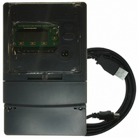
REF DESIGN MCP3909 3PH ENGY MTR
Manufacturer
Microchip Technology
Datasheets
1.MCP3909T-ISS.pdf
(44 pages)
2.MCP3909T-ISS.pdf
(104 pages)
3.MCP3909RD-3PH3.pdf
(88 pages)
Specifications of MCP3909RD-3PH1
Main Purpose
Power Management, Energy/Power Meter
Embedded
No
Utilized Ic / Part
MCP3909, PIC18F2520, PIC18F4550
Primary Attributes
3-Ph, 220 VAC, In Case, LCD, USB, GUI
Secondary Attributes
Opto-Isolated Interface for Safety
Operating Voltage
220 V
Operating Current
5 A
Description/function
Energy Meter
For Use With/related Products
MCP3909
Lead Free Status / RoHS Status
Not applicable / Not applicable


4.1
4.2
© 2009 Microchip Technology Inc.
INTRODUCTION
CURRENT/VOLTAGE CALIBRATION
Meter calibration consists of using standard electrical power equipment that supplies
the power to the meter and calculates the error and correction factor at each calibration
point. This equipment must be accurate in order to calibrate the energy meter. The
supplied PC software is then used to send calibration commands and correction factors
down to the dsPIC33F, completing meter calibration.
Why Is Calibration Necessary?
An energy meter usually consists of errors due to transformers, V
gain errors, and other passive component errors. Energy meters are factory calibrated
before shipping to eliminate the impact from such elements and reduce the error. The
non-linearity and inconsistency of signals in the path of sampling circuit and A/D
conversion circuit cannot be ignored in high-accuracy measurement. The impact needs
to be corrected to improve measurement accuracy.
The calibration described in this chapter are calibrated with the help of the PC software
PM_Viewer, described in detail in the next chapter. To summarize the process, the
measurement error is fed into the software, and the data is then sent to the meter to via
the UART. The details of this procedure are detailed in the next chapter, "PC Software".
Current and voltage calibration is a ratio error calibration from the upper computer by
sending commands and data for correction to the MCU. The dsPIC33F will call a
firmware module after receiving the command from the host PC. The flow is as follows:
1. Determine the phase to be calibrated and the magnitude of current and voltage
2. Calculate the calibration coefficient of the ratio error by the ratio of standard value
3. Multiply the original coefficient by calibration coefficient and obtain the calibration
4. Store the final calibration coefficient after correction into EEPROM.
Since the dynamic range of the voltage channel is usually very small, single-point
calibration is enough to meet the accuracy requirements for full range. However, the
dynamic range of the current channel is larger, and the transformer has different ratio
errors at different current loads.
The MCP3909 device’s current channel, CH0, contains a PGA with gain options of 1,
2, 8, 16. For high-accuracy energy meters, current ratio error needs to be segmented
and calibrated for different current loads. The ratio error calibration of current channel
uses a two-point calibration method. One point is calibrated when the load is at the
rated current (I
nal input condition (0.1 I
being applied to the meter, and read measurement (RMS) values of that channel.
received to the measured value.
coefficient after correction.
Chapter 4. Meter Calibration
Note: Voltage and current calibration is a two step process using 100% and
ENERGY METER REFERENCE DESIGN
B
10% I
) and the PGA gain is 1. The second point is calibrated under small-sig-
B
.
B
) and the PGA gain is 16.
MCP3909 / DSPIC33F 3-PHASE
REF
tolerance, ADC
DS51723A-page 39
Related parts for MCP3909RD-3PH1
Image
Part Number
Description
Manufacturer
Datasheet
Request
R

Part Number:
Description:
BOARD DES MCP3909 ENERGY METER
Manufacturer:
Microchip Technology
Datasheet:

Part Number:
Description:
REF DESIGN FOR MCP3909 W/18F2520
Manufacturer:
Microchip Technology
Datasheet:

Part Number:
Description:
Manufacturer:
Microchip Technology Inc.
Datasheet:
Part Number:
Description:
Manufacturer:
Microchip Technology Inc.
Datasheet:
Part Number:
Description:
Manufacturer:
Microchip Technology Inc.
Datasheet:
Part Number:
Description:
Manufacturer:
Microchip Technology Inc.
Datasheet:
Part Number:
Description:
Manufacturer:
Microchip Technology Inc.
Datasheet:
Part Number:
Description:
Manufacturer:
Microchip Technology Inc.
Datasheet:
Part Number:
Description:
Manufacturer:
Microchip Technology Inc.
Datasheet:
Part Number:
Description:
Manufacturer:
Microchip Technology Inc.
Datasheet: