MCP3909RD-3PH1 Microchip Technology, MCP3909RD-3PH1 Datasheet - Page 100
MCP3909RD-3PH1
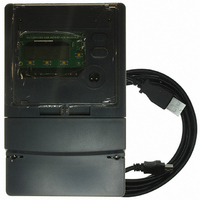
Manufacturer Part Number
MCP3909RD-3PH1
Description
REF DESIGN MCP3909 3PH ENGY MTR
Manufacturer
Microchip Technology
Datasheets
1.MCP3909T-ISS.pdf
(44 pages)
2.MCP3909T-ISS.pdf
(104 pages)
3.MCP3909RD-3PH3.pdf
(88 pages)
Specifications of MCP3909RD-3PH1
Main Purpose
Power Management, Energy/Power Meter
Embedded
No
Utilized Ic / Part
MCP3909, PIC18F2520, PIC18F4550
Primary Attributes
3-Ph, 220 VAC, In Case, LCD, USB, GUI
Secondary Attributes
Opto-Isolated Interface for Safety
Operating Voltage
220 V
Operating Current
5 A
Description/function
Energy Meter
For Use With/related Products
MCP3909
Lead Free Status / RoHS Status
Not applicable / Not applicable


MCP3909 / dsPIC33F 3-Phase Energy Meter Reference Design
DS51723A-page 100
Since the phase lag of a CT's output signal is related to the magnitude of current,
different correction coefficients, K, can be set according to different RMS current
values. In this design, 5 calibration points can be set. If it does not require high-preci-
sion, fewer points can be set to simplify calibration.
If one-time calibration cannot meet the precision requirement, more calibrations can be
done. The new angle error may still be calculated using Equation C-72. The new
correction coefficient is:
EQUATION C-74:
EQUATION C-75:
C.16.0.1 PHASE LAG COMPENSATION WHEN FREQUENCY VARIES
For the same current intensity, the signal delay caused by the CT is the same. When
the frequency of the input signal varies, the phase lag will be different. Normally,
calibration is done at 50 Hz. When the frequency varies, if the same phase lag
compensation coefficient for 50 Hz is still used, it will cause an error in the power
measurement. In most cases, the frequency varies in a small range (test specification
requires ±2.5%), so it has little effect on the measurement accuracy. For meters with
an accuracy of 0.5s or above, this measurement error can be ignored. But for 0.2s
meters, the error cannot be ignored and the frequency variation needs to be corrected
during calculation.
The phase lag compensation coefficient k
Assuming that the freqnency is 50 Hz, the signal delay caused by CT is t, then after
correction, the compensation coefficient k
EQUATION C-76:
EQUATION C-77:
When frequency varies, assuming that the frequency offset is Δf, i.e. the input signal
frequency is 50 + Δf, then the compensation coefficient will be:
EQUATION C-78:
EQUATION C-79:
k'
k'
1
2
=
=
cos
k'
sin
k'
1
2
(
(
k
=
k
=
Δϕ
Δϕ
1
2
cos
=
sin
=
1
1
+
+
cos
Δϕ
Δ
sin
Δϕ
Δϕ
ϕ
Δϕ
Δ
=
=
2
2
ϕ
)
)
cos
sin
=
=
=
=
1
1
and k
and k
k
(
k
cos
sin
(
2
t
1
t
⋅
⋅
⋅
⋅
(
(
(
(
cos
cos
t 50 2
50
t 50 2
50
⋅
2
2
⋅
+
Δϕ
Δϕ
are corrected during calculation.
will be:
+
Δ
⋅
⋅
Δ
2
2
f
f
–
) 2
–
π
) 2
π
⋅
)
⋅
k
k
)
1
2
π
π
⋅
⋅
© 2009 Microchip Technology Inc.
)
)
sin
sin
Δϕ
Δϕ
2
2
Related parts for MCP3909RD-3PH1
Image
Part Number
Description
Manufacturer
Datasheet
Request
R

Part Number:
Description:
BOARD DES MCP3909 ENERGY METER
Manufacturer:
Microchip Technology
Datasheet:

Part Number:
Description:
REF DESIGN FOR MCP3909 W/18F2520
Manufacturer:
Microchip Technology
Datasheet:

Part Number:
Description:
Manufacturer:
Microchip Technology Inc.
Datasheet:
Part Number:
Description:
Manufacturer:
Microchip Technology Inc.
Datasheet:
Part Number:
Description:
Manufacturer:
Microchip Technology Inc.
Datasheet:
Part Number:
Description:
Manufacturer:
Microchip Technology Inc.
Datasheet:
Part Number:
Description:
Manufacturer:
Microchip Technology Inc.
Datasheet:
Part Number:
Description:
Manufacturer:
Microchip Technology Inc.
Datasheet:
Part Number:
Description:
Manufacturer:
Microchip Technology Inc.
Datasheet:
Part Number:
Description:
Manufacturer:
Microchip Technology Inc.
Datasheet: