Z8FMC160100KIT Zilog, Z8FMC160100KIT Datasheet - Page 130
Z8FMC160100KIT
Manufacturer Part Number
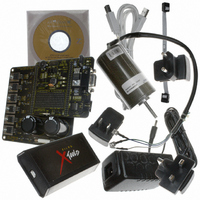
Z8FMC160100KIT
Description
KIT DEV FOR Z8 ENCORE Z8FMC16100
Manufacturer
Zilog
Series
Z8 Encore! MC™r
Datasheets
1.Z8FMC160100KIT.pdf
(7 pages)
2.Z8FMC160100KIT.pdf
(383 pages)
3.Z8FMC160100KIT.pdf
(20 pages)
Specifications of Z8FMC160100KIT
Main Purpose
Power Management, Motor Control
Embedded
Yes, MCU, 8-Bit
Utilized Ic / Part
Z8FMC16100
Primary Attributes
3-Ph DC Motors
Secondary Attributes
Graphic User Interface
Processor To Be Evaluated
Z8FMC16100
Data Bus Width
8 bit
Interface Type
USB
For Use With
269-4664 - KIT ACC OPTO-ISO USB SMART CABLE269-4661 - KIT ACC ETHERNET SMART CABLE269-4539 - KIT ACCESSORY USB SMART CABLE
Lead Free Status / RoHS Status
Contains lead / RoHS non-compliant
Other names
269-3639


Z8FMC16100 Series Flash MCU
Product Specification
118
UART interrupts to go inactive until the next address byte. If the new frame’s address
matches the LIN-UART’s, then the data in the new frame is processed.
The second scheme is enabled by setting
to
and writing the LIN-UART’s
MPMD[1:0]
10B
address into the LIN-UART Address Compare register. This mode introduces more
hardware control, interrupting only on frames that match the LIN-UART’s address. When
an incoming address byte does not match the LIN-UART’s address, it is ignored. All
successive data bytes in this frame are also ignored. When a matching address byte occurs,
an interrupt is issued and further interrupts occur on each successive data byte. The first
data byte in the frame has
in the LIN-UART Status 1 register. When the next
NEWFRM=1
address byte occurs, the hardware compares it to the LIN-UART’s address. If there is a
match, the interrupt occurs and the NEWFRM bit is set for the first byte of the new frame. If
there is no match, the LIN-UART ignores all incoming bytes until the next address match.
The third scheme is enabled by setting
to
and by writing the LIN-
MPMD[1:0]
11B
UART’s address into the LIN-UART Address Compare register. This mode is identical to
the second scheme, except that there are no interrupts on address bytes. The first data byte
of each frame remains accompanied by a
assertion.
NEWFRM
LIN Protocol Mode
The LIN protocol as supported by the LIN-UART module is defined in revision 2.0 of the
LIN Specification Package. The LIN protocol specification covers all aspects of
transferring information between LIN Master and Slave devices using message frames
including error detection and recovery, sleep mode and wake up from sleep mode. The
LIN-UART hardware in LIN mode provides character transfers to support the LIN
protocol including BREAK transmission and detection, WAKE-UP transmission and
detection, and slave autobauding. Part of the error detection of the LIN protocol is for both
master and slave devices to monitor their receive data when transmitting.
If the receive and transmit data streams do not match, the LIN-UART asserts the
bit
PLE
(physical layer error bit in Status0 register). The message frame timeout aspect of the
protocol is left to software, requiring the use of an additional general purpose timer. The
LIN mode of the LIN-UART does not provide any hardware support for computing/
verifying the checksum field or verifying the contents of the Identifier field. These fields
are treated as data and are not interpreted by hardware. The checksum calculation/
verification can easily be implemented in software through the ADC (Add with Carry)
instruction.
The LIN bus contains a single master and one or more slaves. The LIN master is
responsible for transmitting the message frame header which consists of the Break, Synch
and Identifier fields. Either the master or one of the slaves transmits the associated
response section of the message which consists of data characters followed by a checksum
character.
PS024613-0910
LIN Protocol Mode
Related parts for Z8FMC160100KIT
Image
Part Number
Description
Manufacturer
Datasheet
Request
R

Part Number:
Description:
Communication Controllers, ZILOG INTELLIGENT PERIPHERAL CONTROLLER (ZIP)
Manufacturer:
Zilog, Inc.
Datasheet:

Part Number:
Description:
KIT DEV FOR Z8 ENCORE 16K TO 64K
Manufacturer:
Zilog
Datasheet:

Part Number:
Description:
KIT DEV Z8 ENCORE XP 28-PIN
Manufacturer:
Zilog
Datasheet:

Part Number:
Description:
DEV KIT FOR Z8 ENCORE 8K/4K
Manufacturer:
Zilog
Datasheet:

Part Number:
Description:
KIT DEV Z8 ENCORE XP 28-PIN
Manufacturer:
Zilog
Datasheet:

Part Number:
Description:
DEV KIT FOR Z8 ENCORE 4K TO 8K
Manufacturer:
Zilog
Datasheet:
Part Number:
Description:
CMOS Z8 microcontroller. ROM 16 Kbytes, RAM 256 bytes, speed 16 MHz, 32 lines I/O, 3.0V to 5.5V
Manufacturer:
Zilog, Inc.
Datasheet:
Part Number:
Description:
Low-cost microcontroller. 512 bytes ROM, 61 bytes RAM, 8 MHz
Manufacturer:
Zilog, Inc.
Datasheet:
Part Number:
Description:
Z8 4K OTP Microcontroller
Manufacturer:
Zilog, Inc.
Datasheet:
Part Number:
Description:
CMOS SUPER8 ROMLESS MCU
Manufacturer:
Zilog, Inc.
Datasheet:
Part Number:
Description:
SL1866 CMOSZ8 OTP Microcontroller
Manufacturer:
Zilog, Inc.
Datasheet:
Part Number:
Description:
SL1866 CMOSZ8 OTP Microcontroller
Manufacturer:
Zilog, Inc.
Datasheet:
Part Number:
Description:
OTP (KB) = 1, RAM = 125, Speed = 12, I/O = 14, 8-bit Timers = 2, Comm Interfaces Other Features = Por, LV Protect, Voltage = 4.5-5.5V
Manufacturer:
Zilog, Inc.
Datasheet:
Part Number:
Description:
Manufacturer:
Zilog, Inc.
Datasheet: