AC164127-6 Microchip Technology, AC164127-6 Datasheet - Page 63
AC164127-6
Manufacturer Part Number
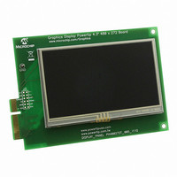
AC164127-6
Description
BOARD 4.3" LCD TOUCH SCREEN
Manufacturer
Microchip Technology
Datasheet
1.AC164127-6.pdf
(64 pages)
Specifications of AC164127-6
Main Purpose
Displays, LCD Display
Primary Attributes
4.3" WQVGA, Touch Screen
Secondary Attributes
Parallel Interface
Lead Free Status / RoHS Status
Lead free / RoHS Compliant
For Use With
AC164127-5 - BOARD GRAPH LCD CNTLR PICTAIL
Utilized Ic / Part
-
Embedded
-
Lead Free Status / Rohs Status
Lead free / RoHS Compliant
Available stocks
Company
Part Number
Manufacturer
Quantity
Price
Company:

Part Number:
AC164127-6
Manufacturer:
Microchip Technology
Quantity:
135


B
Building Code...................................................................... 22
C
Configuration
Connectors.......................................................................... 49
CTMU Touch Sensors ........................................................ 37
Current Measurement ......................................................... 47
Customer Notification Service............................................... 9
Customer Support ................................................................. 9
D
Debugging Code ................................................................. 27
Demonstration Application (pre-programmed) .................... 17
Demonstration Programs .................................................... 15
Development Board Block Diagram .................................... 32
Diagrams
Documentation
E
External SRAM ................................................................... 43
2010 Microchip Technology Inc.
Analog Input (Potentiometer) ...................................... 37
Board Configuration vs Availability of Features .......... 35
EPMP Alternate Configuration .................................... 48
External Memory
Graphics Port .............................................................. 41
Jumper Locations.................................................. 34, 50
LEDs ........................................................................... 37
PICtail Plus Connector
PICtail Plus Connector................................................ 46
Push Button Switches ................................................. 36
Touch Sensors............................................................ 37
UART .......................................................................... 39
USB....................................................................... 38–39
Block Diagram............................................................. 32
Configuring User-Defined Features ............................ 36
Current Measurement ................................................. 48
Development Board Layout ........................................ 12
Flash Memory Configuration....................................... 45
Jumper Locations........................................................ 34
PICtail Plus Configuration Resistors ........................... 47
SRAM Configuration ................................................... 44
Touch Controller and Backlight Configuration ............ 42
UART Configuration.................................................... 40
USB Mode Configuration ............................................ 38
Conventions .................................................................. 6
Layout ........................................................................... 5
Flash Memory ..................................................... 45
SRAM ................................................................. 43
Backlight Control................................................. 43
Touch Screen Interface ...................................... 42
Hardware Modifications .......................... 47, 59–62
RX Signal and Backlight ..................................... 41
TX Remapping .................................................... 40
Index
F
Flash Memory ..................................................................... 45
I
Internet Address ................................................................... 8
L
Loading a Software Project................................................. 20
M
MCLR ....................................................................... 33, 16, 8
O
Oscillator Options ............................................................... 33
P
PCB Layout Features ......................................................... 32
PICtail Plus Connector Pin Mapping................................... 60
Potentiometer ..................................................................... 37
Power Requirements .......................................................... 13
Power Supply Options ........................................................ 33
Programming the PIC24FJ256DA210 ................................ 23
Programming/Debugging Interface..................................... 33
Push Button Switches......................................................... 36
R
Reading, Recommended ...................................................... 7
Reset Switch....................................................................... 33
Running Code..................................................................... 26
S
Schematics ................................................................... 51–57
Software for Application Development................................ 16
U
UART .................................................................................. 39
USB On-the-Go mode ........................................................ 39
Using Breakpoints and Mouseovers ................................... 28
Using Watch Windows........................................................ 29
W
WWW Address ..................................................................... 8
DEVELOPMENT BOARD
PIC24FJ256DA210
USER’S GUIDE
DS51911A-page 63
Related parts for AC164127-6
Image
Part Number
Description
Manufacturer
Datasheet
Request
R

Part Number:
Description:
Fuses 16A 415V AC/250V DC
Manufacturer:
Apex Tool Group (Formerly Cooper Tools)

Part Number:
Description:
Manufacturer:
Microchip Technology Inc.
Datasheet:
Part Number:
Description:
Manufacturer:
Microchip Technology Inc.
Datasheet:
Part Number:
Description:
Manufacturer:
Microchip Technology Inc.
Datasheet:
Part Number:
Description:
Manufacturer:
Microchip Technology Inc.
Datasheet:
Part Number:
Description:
Manufacturer:
Microchip Technology Inc.
Datasheet:
Part Number:
Description:
Manufacturer:
Microchip Technology Inc.
Datasheet:
Part Number:
Description:
Manufacturer:
Microchip Technology Inc.
Datasheet:
Part Number:
Description:
Manufacturer:
Microchip Technology Inc.
Datasheet: