AC164127-6 Microchip Technology, AC164127-6 Datasheet - Page 47
AC164127-6
Manufacturer Part Number
AC164127-6
Description
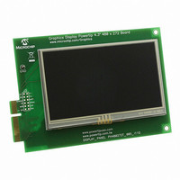
BOARD 4.3" LCD TOUCH SCREEN
Manufacturer
Microchip Technology
Datasheet
1.AC164127-6.pdf
(64 pages)
Specifications of AC164127-6
Main Purpose
Displays, LCD Display
Primary Attributes
4.3" WQVGA, Touch Screen
Secondary Attributes
Parallel Interface
Lead Free Status / RoHS Status
Lead free / RoHS Compliant
For Use With
AC164127-5 - BOARD GRAPH LCD CNTLR PICTAIL
Utilized Ic / Part
-
Embedded
-
Lead Free Status / Rohs Status
Lead free / RoHS Compliant
Available stocks
Company
Part Number
Manufacturer
Quantity
Price
Company:

Part Number:
AC164127-6
Manufacturer:
Microchip Technology
Quantity:
135


2010 Microchip Technology Inc.
4.4.6.1
Depending on the PICtail Plus Daughter Board to be used, hardware modification to
the development board may be required. The modifications re-route different signals
from the microcontroller, particularly EPMP signals, to different pins of the connector.
All changes consist of placing
tions, or removing existing resistors in other places to disable existing connections. All
of the resistors are located in a single group adjacent to the Flash memory area, shown
in Figure 4-10. They are also shown as a single group in Figure A-6 of the development
board schematic.
FIGURE 4-10:
For additional information on the configuration resistors, as well as specific modifica-
tions for particular daughter boards, please refer to Appendix B. “Modifications for
PICtail Plus Daughter Boards”.
4.4.7
To provide additional information on developing hardware solutions, the development
board includes current measurement points at three locations. These permit the current
drawn by the different branches of the development board to be measured separately.
The measurement points are unpopulated jumpers at JP1, JP2 and JP3 (Figure 4-11,
callouts 1,2 and 3, respectively). To measure current, cut the trace on the reverse side
of the board that shorts the two vias for the jumper, then insert the current measuring
device between the two vias.
JP3 can be used to measure the total current drawn by the board from the 9V power
supply. JP1 can be used to measure the total current (at 3.3V) drawn by the microcon-
troller, and JP2 can be used to measure the total current drawn by the remaining 3.3V
branch of the board. The current drawn by the 5V branch can be measured by subtract-
ing the sum of the currents of JP1 and JP2 from the total current measured at JP3.
DAUGHTER BOARD-SPECIFIC HARDWARE MODIFICATIONS
Current Measurement
LOCATION OF CONFIGURATION RESISTORS
Development Board Hardware
0
resistors in designated areas to enable the connec-
M
DS51911A-page 47
Related parts for AC164127-6
Image
Part Number
Description
Manufacturer
Datasheet
Request
R

Part Number:
Description:
Fuses 16A 415V AC/250V DC
Manufacturer:
Apex Tool Group (Formerly Cooper Tools)

Part Number:
Description:
Manufacturer:
Microchip Technology Inc.
Datasheet:
Part Number:
Description:
Manufacturer:
Microchip Technology Inc.
Datasheet:
Part Number:
Description:
Manufacturer:
Microchip Technology Inc.
Datasheet:
Part Number:
Description:
Manufacturer:
Microchip Technology Inc.
Datasheet:
Part Number:
Description:
Manufacturer:
Microchip Technology Inc.
Datasheet:
Part Number:
Description:
Manufacturer:
Microchip Technology Inc.
Datasheet:
Part Number:
Description:
Manufacturer:
Microchip Technology Inc.
Datasheet:
Part Number:
Description:
Manufacturer:
Microchip Technology Inc.
Datasheet: