AC164127-6 Microchip Technology, AC164127-6 Datasheet - Page 43
AC164127-6
Manufacturer Part Number
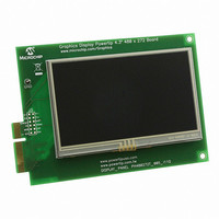
AC164127-6
Description
BOARD 4.3" LCD TOUCH SCREEN
Manufacturer
Microchip Technology
Datasheet
1.AC164127-6.pdf
(64 pages)
Specifications of AC164127-6
Main Purpose
Displays, LCD Display
Primary Attributes
4.3" WQVGA, Touch Screen
Secondary Attributes
Parallel Interface
Lead Free Status / RoHS Status
Lead free / RoHS Compliant
For Use With
AC164127-5 - BOARD GRAPH LCD CNTLR PICTAIL
Utilized Ic / Part
-
Embedded
-
Lead Free Status / Rohs Status
Lead free / RoHS Compliant
Available stocks
Company
Part Number
Manufacturer
Quantity
Price
Company:

Part Number:
AC164127-6
Manufacturer:
Microchip Technology
Quantity:
135


2010 Microchip Technology Inc.
4.4.4.5
Depending on the display glass being used, backlight control is provided as an
ON/OFF signal, or as a PWM pulse train for a continuous range of brightness. Jumper
JP12 (Figure 4-7, callout 2) selects which signal is enabled on display connector V1.
By default, backlight control is disconnected (position 2-4).
• To enable BKLT_EN (ON/OFF), set JP12 to bridge 2-3.
• To enable BKLT_PWM (PWM controlled contrast), set JP12 to bridge 1-2.
4.4.5
The PIC24FJ256DA210 can be used to create a graphics solution without any external
memory resources. However, in cases where the application requires a higher color
depth (8 bits per pixel or more), or larger storage for images and data, external SRAM
and Flash memory devices are provided on the development board.
Both SRAM and parallel Flash memory can be enabled at the same time. The
Enhanced Parallel Master Port module (EPMP) accesses memory on both devices with
the same data and address lines. PMCS1 is used as the Chip Select signal for the
SRAM, and PMCS2 is used for the parallel Flash. Note, however, that configuring a
memory addressing size option for one device selects the same size for the other.
If all 19 address lines of the EPMP are not required, PMA17 and PMA18 can be con-
figured for other purposes. PMA17 can be used to control LED D4, while PMA18 can
be reconfigured to function as an I/O on the PICtail Plus Expansion port.
For more information on using the EPMP, refer to “Enhanced Parallel Master Port
(EPMP)” (DS39730) for more information.
4.4.5.1
The PIC24FJ256DA210 Development Board is provided with 512 Kbyte of external
SRAM, populating U6. By default, only 256 out of the 512 KByte is enabled; this allows
PMA17 to control LED D4 in the default board default configuration. If required, the
SRAM may be upgraded to 1 MByte by replacing U6 with a different device. The SRAM
interfaces with the microcontroller through the EPMP interface. Use of external SRAM
is optional if internal 24/96 Kbyte RAM of PIC24FJ256DA210 cannot accommodate the
required frame buffer size for a specific color depth and resolution combination.
SRAM access time is an important aspect of the interface to the EPMP port. In most
QVGA based applications, the use of a 55 ns access time is enough to meet the refresh
requirements of the display. The use of a 10 ns access time SRAM on the board is due
to the fact that VGA resolution display, which requires more bandwidth, can also be
driven by the development board.
The SRAM can be configured for one of three memory address ranges, shown in
Table 4-7.
TABLE 4-7:
256 Kbyte
512 Kbyte
Note:
(default)
1 Mbyte
Size
BACKLIGHT CONTROL
On-Board External Memory
EXTERNAL SRAM
If either of the backlight control modes is selected, access to the UART will be
disabled. See Section 4.4.3.2 “UART and Display Backlight (RX Signal)”
for more information.
SRAM MEMORY OPTIONS
Bridged
Bridged
Open
JP11
Development Board Hardware
Open
Open
R63
0
Active EPMP
PMA<16:0>
PMA<17:0>
PMA<18:0>
Address
Lines
IS61WV51216BLL-10TLI
Recommended Part #s
IS61LV25616AL-10TL
AS7C34098A
IDT71V416S
DS51911A-page 43
Related parts for AC164127-6
Image
Part Number
Description
Manufacturer
Datasheet
Request
R

Part Number:
Description:
Fuses 16A 415V AC/250V DC
Manufacturer:
Apex Tool Group (Formerly Cooper Tools)

Part Number:
Description:
Manufacturer:
Microchip Technology Inc.
Datasheet:
Part Number:
Description:
Manufacturer:
Microchip Technology Inc.
Datasheet:
Part Number:
Description:
Manufacturer:
Microchip Technology Inc.
Datasheet:
Part Number:
Description:
Manufacturer:
Microchip Technology Inc.
Datasheet:
Part Number:
Description:
Manufacturer:
Microchip Technology Inc.
Datasheet:
Part Number:
Description:
Manufacturer:
Microchip Technology Inc.
Datasheet:
Part Number:
Description:
Manufacturer:
Microchip Technology Inc.
Datasheet:
Part Number:
Description:
Manufacturer:
Microchip Technology Inc.
Datasheet: