AC164127-6 Microchip Technology, AC164127-6 Datasheet - Page 38
AC164127-6
Manufacturer Part Number
AC164127-6
Description
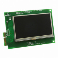
BOARD 4.3" LCD TOUCH SCREEN
Manufacturer
Microchip Technology
Datasheet
1.AC164127-6.pdf
(64 pages)
Specifications of AC164127-6
Main Purpose
Displays, LCD Display
Primary Attributes
4.3" WQVGA, Touch Screen
Secondary Attributes
Parallel Interface
Lead Free Status / RoHS Status
Lead free / RoHS Compliant
For Use With
AC164127-5 - BOARD GRAPH LCD CNTLR PICTAIL
Utilized Ic / Part
-
Embedded
-
Lead Free Status / Rohs Status
Lead free / RoHS Compliant
Available stocks
Company
Part Number
Manufacturer
Quantity
Price
Company:

Part Number:
AC164127-6
Manufacturer:
Microchip Technology
Quantity:
135


PIC24FJ256DA210 Development Board User’s Guide
DS51911A-page 38
4.4.2
The PIC24FJ256DA210 Development Board supports three distinct full-speed USB
modes: Host mode (default), Device mode, and USB On-The-Go (OTG) mode.
Although the particular operating mode of the microcontroller is determined by the
application and device configuration, the development board hardware also needs to
be configured to suit the mode as well. These are selected by the USB mode jumpers
(Figure 4-4, callout 1). Additional current sense options for Host and OTG modes are
configured with setting I/O jumpers and modifying certain on-board resistors (callouts
2 and 3).
FIGURE 4-4:
4.4.2.1
To enable the USB Host Mode:
1. Install jumper JP6.
2. Remove jumpers JP5 and JP7.
3. If the application requires detection of drawn current by the device on the USB
In Host mode, use J4 (Type A Female USB connector) to connect to an external USB
device.
4.4.2.2
To enable USB Device mode:
1. Install jumper JP7.
2. Remove jumpers JP5 and JP6.
In this mode, use J2 (Type Mini B Female USB connector) to connect to an external
USB Host.
Note:
line, enable the detection of an analog OVERCURRENT signal at pin AN19/RG8
of the microcontroller as follows (Figure 4-4, callout 2):
a) Open jumper JP13 (disconnects CTMU_PAD1, LED D1 and Switch S1).
b) Populate R26 with a
c) If installed, remove resistor R27. (R27 may have been installed if the USB
1
OTG mode was previously enabled. See Section 4.4.3.1 “UART and USB
OTG Mode (TX Remapping)” for more information.)
USB Connectivity
USB HOST MODE (DEFAULT)
USB DEVICE MODE
Only one USB mode may be enabled in hardware at any time.
CONFIGURING USB MODES
0
resistor.
M
2010 Microchip Technology Inc.
2
3
Related parts for AC164127-6
Image
Part Number
Description
Manufacturer
Datasheet
Request
R

Part Number:
Description:
Fuses 16A 415V AC/250V DC
Manufacturer:
Apex Tool Group (Formerly Cooper Tools)

Part Number:
Description:
Manufacturer:
Microchip Technology Inc.
Datasheet:
Part Number:
Description:
Manufacturer:
Microchip Technology Inc.
Datasheet:
Part Number:
Description:
Manufacturer:
Microchip Technology Inc.
Datasheet:
Part Number:
Description:
Manufacturer:
Microchip Technology Inc.
Datasheet:
Part Number:
Description:
Manufacturer:
Microchip Technology Inc.
Datasheet:
Part Number:
Description:
Manufacturer:
Microchip Technology Inc.
Datasheet:
Part Number:
Description:
Manufacturer:
Microchip Technology Inc.
Datasheet:
Part Number:
Description:
Manufacturer:
Microchip Technology Inc.
Datasheet: