AC164127-6 Microchip Technology, AC164127-6 Datasheet - Page 32
AC164127-6
Manufacturer Part Number
AC164127-6
Description
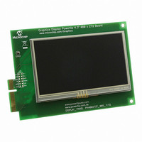
BOARD 4.3" LCD TOUCH SCREEN
Manufacturer
Microchip Technology
Datasheet
1.AC164127-6.pdf
(64 pages)
Specifications of AC164127-6
Main Purpose
Displays, LCD Display
Primary Attributes
4.3" WQVGA, Touch Screen
Secondary Attributes
Parallel Interface
Lead Free Status / RoHS Status
Lead free / RoHS Compliant
For Use With
AC164127-5 - BOARD GRAPH LCD CNTLR PICTAIL
Utilized Ic / Part
-
Embedded
-
Lead Free Status / Rohs Status
Lead free / RoHS Compliant
Available stocks
Company
Part Number
Manufacturer
Quantity
Price
Company:

Part Number:
AC164127-6
Manufacturer:
Microchip Technology
Quantity:
135


PIC24FJ256DA210 Development Board User’s Guide
4.3
DS51911A-page 32
GENERAL HARDWARE FEATURES
FIGURE 4-1:
4.3.1
The PIC24FJ256DA210 Development Board uses several design strategies to provide
a stable demonstration and development environment. Users should note these
features and design tips when developing their own graphic applications.
The development board uses a four-layer PCB design; this allows high-frequency
signals to be routed in a way to avoid crosstalk between data signals. It also gives
additional noise protection due to improved grounding.
For additional noise protection, oscillator circuits and crystals are laid out with appro-
priate grounding and guard rings. The layout guidelines are described in Section 2.
“Guidelines for Getting Started with 16-Bit Microcontrollers” of the device data
sheet.
Each group of color signals (Red, Green and Blue) is routed together to reduce inter-
color crosstalk. This means, for example, that Red signals are close together and do
not mix with Green and/or Blue signals. Ideally, it is recommended to run a ground wire
or trace between groups of color signals to reduce crosstalk. Also, the traces for color
data should be as close to equal length as possible, and avoid the use of vias wherever
possible.
4.3.2
The development board is supplied with the PIC24FJ256DA210 microcontroller
directly soldered to the board at U2. The device is installed with the notched corner (pin
1) oriented to the lower right. Vias are provided around the device, which allow access
to all microcontroller signals; this is labelled on the board as U9. A riser may be installed
here to facilitate connections to user added components in the prototyping area.
PCB Layout
Microcontroller
512 KByte
512 Kbyte
FLASH
SRAM
Device
OTG
USB
USB
Host
USB
PIC24FJ256DA210 DEVELOPMENT BOARD BLOCK
DIAGRAM
(TFT, CSTN, MSTN)
Display Panel
EPMP
USB
3 CTMU/
4 LEDs
PIC24FJ256DA210
Connector
DISPLAY
3 Buttons/
Switches
Resistive
Screen
Touch
SPI
Potentiometer
Display
SPI
R3
UART
2010 Microchip Technology Inc.
SPI FLASH
Transceiver
PICtail™ Plus
Connector
(16MBit)
RS-232
ICSP™
Related parts for AC164127-6
Image
Part Number
Description
Manufacturer
Datasheet
Request
R

Part Number:
Description:
Fuses 16A 415V AC/250V DC
Manufacturer:
Apex Tool Group (Formerly Cooper Tools)

Part Number:
Description:
Manufacturer:
Microchip Technology Inc.
Datasheet:
Part Number:
Description:
Manufacturer:
Microchip Technology Inc.
Datasheet:
Part Number:
Description:
Manufacturer:
Microchip Technology Inc.
Datasheet:
Part Number:
Description:
Manufacturer:
Microchip Technology Inc.
Datasheet:
Part Number:
Description:
Manufacturer:
Microchip Technology Inc.
Datasheet:
Part Number:
Description:
Manufacturer:
Microchip Technology Inc.
Datasheet:
Part Number:
Description:
Manufacturer:
Microchip Technology Inc.
Datasheet:
Part Number:
Description:
Manufacturer:
Microchip Technology Inc.
Datasheet: