P0307 Terasic Technologies Inc, P0307 Datasheet - Page 15
P0307
Manufacturer Part Number
P0307
Description
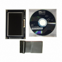
KIT DEV 4.3" LCD TOUCH PANEL
Manufacturer
Terasic Technologies Inc
Specifications of P0307
Accessory Type
NTSC/PAL TV Player
For Use With/related Products
DE2, DE1
Lead Free Status / RoHS Status
Lead free / RoHS Compliant
Other names
TRDB_LTM
Available stocks
Company
Part Number
Manufacturer
Quantity
Price
Company:

Part Number:
P0307
Manufacturer:
Terasic Technologies Inc
Quantity:
135


This section will describe how to obtain the X/Y coordinates of the touch point from the AD converter.
12-bit analog to digital converter (ADC) for digitizing x and y coordinates of touch points applied to the touch
screen. The coordinates of the touch point stored in the AD7843 can be obtained by the serial port interface.
ADC_PENIRQ_n outputted from the ADC. By connecting a pull high resistor, the ADC_PENIRQ_n output
remains high normally. When the touch screen connected to the ADC is touched via a pen or finger, the
ADC_PENIRQ_n output goes low, initiating an interrupt to a FPGA that can then instruct a control word to be
written to the ADC via the serial port interface.
start, channel addressing, ADC conversion resolution, configuration, and power-down of the ADC. The
detailed information on the order and description of these control bits can be found from the datasheet of the
ADC in the DATASHEET folder on the LTM System CD-ROM.
The LTM also equipped with an Analog Devices AD7843 touch screen digitizer chip. The AD7843 is a
To obtain the coordinate from the ADC, the first thing users need to do is monitor the interrupt signal
The control word provided to the ADC via the DIN pin is shown in Table 3.5. This provides the conversion
3-3 The serial interface of the AD converter
MSB
6-4
1,0
Bit
S
7
3
2
Mnemonic
S E R
PD1,PD0
MODE
A2-A0
A2
S
/
D E F
Start Bit. The control word starts with the first high bit on DIN. A
new control word can start every 15th DCLK cycle when in the
12-bit conversion mode, or every 11th DCLK cycle when in 8-bit
conversion mode.
Channel Select Bits. These three address bits, along with the
switches, and reference inputs.
12-Bit/8-Bit Conversion Select Bit. This bit controls the resolution
of the following conversion. With 0 in this bit, the
conversion has a 12-bit resolution, or with 1 in this bit, the
conversion has a 8-bit resolution.
Single-Ended/Differential Reference Select Bit. Along with Bits
A2– A0, this bit controls the setting of the multiplexer
input, switches, and reference inputs.
Power Management Bits. These two bits decode the power-down
mode of the AD7843.
S E R
A1
/
D E F
bit, control the setting of the multiplexer input,
A0
13
MODE
Comment
S E R
/
D E F
PD1
LSB
PD0
Using the LTM
Related parts for P0307
Image
Part Number
Description
Manufacturer
Datasheet
Request
R

Part Number:
Description:
MODULE DIGITAL CAMERA 5MP (D5M)
Manufacturer:
Terasic Technologies Inc
Datasheet:

Part Number:
Description:
DE2-70 CALL FOR ACADEMIC PRICING
Manufacturer:
Terasic Technologies Inc
Datasheet:

Part Number:
Description:
USB BLASTER CABLE
Manufacturer:
Terasic Technologies Inc
Datasheet:

Part Number:
Description:
BOARD ADAPTER HSMC TO GPIO
Manufacturer:
Terasic Technologies Inc
Datasheet:

Part Number:
Description:
BOARD ADAPTER THDB-SUM
Manufacturer:
Terasic Technologies Inc
Datasheet:

Part Number:
Description:
DAUGHTER BOARD AD/DA GPIO ADA
Manufacturer:
Terasic Technologies Inc

Part Number:
Description:
DAUGHTER BOARD AD/DA HSMC ADA
Manufacturer:
Terasic Technologies Inc

Part Number:
Description:
KIT MAX II MICRO
Manufacturer:
Terasic Technologies Inc
Datasheet:

Part Number:
Description:
BOARD DEV/EDUCATION ALTERA DE0
Manufacturer:
Terasic Technologies Inc
Datasheet:

Part Number:
Description:
BOARD DEV DE1 ALTERA
Manufacturer:
Terasic Technologies Inc
Datasheet:

Part Number:
Description:
DE2 CALL FOR ACADEMIC PRICING
Manufacturer:
Terasic Technologies Inc

Part Number:
Description:
MODULE DIGITAL CAMERA 1.3MP
Manufacturer:
Terasic Technologies Inc
Datasheet:

Part Number:
Description:
SENSOR CMOS 1.3MEGA (FOR P0349)
Manufacturer:
Terasic Technologies Inc
Datasheet:
Part Number:
Description:
MODULE DIGITAL CAMERA 5MP (D5M)
Manufacturer:
Terasic Technologies Inc
Datasheet: