P0307 Terasic Technologies Inc, P0307 Datasheet - Page 10
P0307
Manufacturer Part Number
P0307
Description
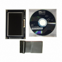
KIT DEV 4.3" LCD TOUCH PANEL
Manufacturer
Terasic Technologies Inc
Specifications of P0307
Accessory Type
NTSC/PAL TV Player
For Use With/related Products
DE2, DE1
Lead Free Status / RoHS Status
Lead free / RoHS Compliant
Other names
TRDB_LTM
Available stocks
Company
Part Number
Manufacturer
Quantity
Price
Company:

Part Number:
P0307
Manufacturer:
Terasic Technologies Inc
Quantity:
135


3
Chapter
This section will describe how to control the register value of the LCD driver IC on the LTM.
The LCD and touch panel module on the LTM is equipped with a LCD driver IC to support three
display resolution and with functions of source driver, serial port interface, timing controller, and
power supply circuits. To control these functions, users can use FPGA to configure the registers in
the LCD driver IC via serial port interface.
Also, there is an analog to digital converter (ADC) on the LTM to convert the analog X/Y coordinates
of the touch point to digital data and output to FPGA through the serial port interface of the ADC.
Both LCD driver IC and ADC serial port interfaces are connected to the FPGA via the 40-pin
expansion header and IDE cable.
Because of the limited number of I/O on the expansion header, the serial interfaces of the LCD
driver IC and ADC need to share the same clock (ADC_DCLK) and chip enable (SCEN) signal I/O
on the expansion header. To avoid both the serial port interfaces may interfere with each other when
sharing the same clock and chip enable signals, the chip enable signal (CS), which is inputted into
the ADC will come up with a logic inverter. Users need to pay attention controlling the shared
signals when designing the serial port interface controller. The detailed register maps of the LCD
driver IC are listed in appendix chapter. The specifications of the serial port interface of the LCD
driver IC are described below.
enable instruction setting. Please notice that in addition to the serial port interface signals, NCLK
input should also be provided while setting the registers. Figure 3.1 and Table 3.1 show the frame
format and timing diagram of the serial port interface. The LCD driver IC recognizes the start of data
The LCD driver IC supports a clock synchronous serial interface as the interface to a FPGA to
3-1 The Serial Port Interface of the LCD Driver IC
This chapter illustrates how to use the LTM including how to control the serial port
interface of the LCD driver IC and AD converter. Also, the timing requirement of
the synchronous signal and RGB data which are outputted to the LCD panel
module will be described.
Using the LTM
8
Chapter 3
Using the LTM
Related parts for P0307
Image
Part Number
Description
Manufacturer
Datasheet
Request
R

Part Number:
Description:
MODULE DIGITAL CAMERA 5MP (D5M)
Manufacturer:
Terasic Technologies Inc
Datasheet:

Part Number:
Description:
DE2-70 CALL FOR ACADEMIC PRICING
Manufacturer:
Terasic Technologies Inc
Datasheet:

Part Number:
Description:
USB BLASTER CABLE
Manufacturer:
Terasic Technologies Inc
Datasheet:

Part Number:
Description:
BOARD ADAPTER HSMC TO GPIO
Manufacturer:
Terasic Technologies Inc
Datasheet:

Part Number:
Description:
BOARD ADAPTER THDB-SUM
Manufacturer:
Terasic Technologies Inc
Datasheet:

Part Number:
Description:
DAUGHTER BOARD AD/DA GPIO ADA
Manufacturer:
Terasic Technologies Inc

Part Number:
Description:
DAUGHTER BOARD AD/DA HSMC ADA
Manufacturer:
Terasic Technologies Inc

Part Number:
Description:
KIT MAX II MICRO
Manufacturer:
Terasic Technologies Inc
Datasheet:

Part Number:
Description:
BOARD DEV/EDUCATION ALTERA DE0
Manufacturer:
Terasic Technologies Inc
Datasheet:

Part Number:
Description:
BOARD DEV DE1 ALTERA
Manufacturer:
Terasic Technologies Inc
Datasheet:

Part Number:
Description:
DE2 CALL FOR ACADEMIC PRICING
Manufacturer:
Terasic Technologies Inc

Part Number:
Description:
MODULE DIGITAL CAMERA 1.3MP
Manufacturer:
Terasic Technologies Inc
Datasheet:

Part Number:
Description:
SENSOR CMOS 1.3MEGA (FOR P0349)
Manufacturer:
Terasic Technologies Inc
Datasheet:
Part Number:
Description:
MODULE DIGITAL CAMERA 5MP (D5M)
Manufacturer:
Terasic Technologies Inc
Datasheet: