SWS600L-24 TDK Corporation, SWS600L-24 Datasheet - Page 12
SWS600L-24
Manufacturer Part Number
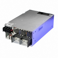
SWS600L-24
Description
POWER SUPPLY 24V 27A SGL OUTPUT
Manufacturer
TDK Corporation
Series
SWSr
Type
Commercialr
Specifications of SWS600L-24
Power Supply Type
Switching (Closed Frame)
Voltage - Output
24V
Number Of Outputs
1
Power (watts)
600W
Applications
Commercial
Voltage - Input
85 ~ 265VAC
Mounting Type
Chassis Mount
1st Output
24 VDC @ 27A
Size / Dimension
7.48" L x 4.72" W x 2.4" H (190mm x 120mm x 61mm)
Power (watts) - Rated
648W
Operating Temperature
-20°C ~ 74°C
Efficiency
84%
Approvals
CSA, DENAN, EN, IEC, UL
Power Supply Output Type
Fixed
No. Of Outputs
1
Output Voltage
24V
Output Current
27A
Power Rating
648W
Input Voltage
85V AC To 265V AC / 120V DC To 350V DC
Brand/series
SWS Series
Configuration
Enclosed
Output
24 VDC @ 27 A
Power, Output
648 W
Primary Type
AC-DC
Special Features
Parallelable, PFC, Remote On/Off, Remote Sense
Voltage, Input
85 to 265/120 to 350 VAC/VDC
Voltage, Output
24 VDC
Input Frequency
47 to 63Hz
Screening Level
Commercial
Operating Temperature Min Deg. C
-20C
Mounting Style
Desktop
Lead Free Status / RoHS Status
Lead free / RoHS Compliant
3rd Output
-
2nd Output
-
4th Output
-
Lead Free Status / Rohs Status
RoHS Compliant part
Other names
285-1742
SWS600L24
SWS600L24
Available stocks
Company
Part Number
Manufacturer
Quantity
Price

Part Number:
SWS600L-24
Quantity:
119


12
SWS
Input voltage range is single phase 85 - 265VAC (47 - 63Hz) or
120 - 350VDC. Input voltage, which is out of specifi cation, may
cause unit damage. Rated input voltage for safety standard
application is 100AC-240VAC (50/60Hz).
Output voltage is set to the rated value at shipment. V.ADJ trim-
mer on the front panel side can be used to adjust the output
voltage within the range specifi ed (refer to specifi cations for
adjustable range).
To turn the trimmer clockwise, the output voltage will be in-
creased. Take note when the output voltage is increased ex-
cessively, over voltage protection (OVP) function may trigger
and output voltage will be shut down.
The OVP function (inverter shutdown method, manual re-
set type) is provided. OVP function operates within
range (refer to specifi cation)
and the output will be shut down when OVP function triggers
(refer to specifi cations for OVP range of each models). To reset
OVP, remove the input of power supply for a few minutes, and
then re-input. Or, use CNT to reset (remote ON/OFF : OFF to
ON). OVP value is fi xed and not to be adjusted externally. Never
apply more than rated output voltage to output terminal, which
may lead to damage. In the case of inductive load, use decou-
pling diode at output line.
The OCP function is provided. OCP characteristic is constant
current limiting, automatic recovery. OCP function operates
when the output current exceeds 105% (24V output model:
101% of peak current) of maximum DC output current speci-
fi cation. The output will be automatically recovered when the
overload condition is cancelled. Never operate the unit under
over current or shorted conditions for more than 30 seconds,
which may lead to damage. OCP setting is fi xed and not to be
adjusted externally.
The OTP function (manual reset type) is provided. When ambi-
ent or internal temperature rises abnormally, OTP function op-
erates and output will be shut down. After shut down, remove
the input and cool it down to reset OTP. Then re-input.
Power failure detection circuit is provided. ALM (Alarm) signal
will turn“High”level to indicate the abnormal status when con-
verter stops. Please take note in parallel or N+1 operation at light
load condition, maybe only one of the power supply operates
and other power supply stops. When the built-in FAN motor of
this power supply unit stops, ALM signal will turn to “High” too.
If the output voltage is decreased to less than 20% of rated
voltage, or decreased rapidly through an external adjustment
mechanism when load is light, the ALM signal may turn “High”.
The ALM signal is isolated from input and output by a photo-
mosfet. It uses the open collector method shown as below.
Input Voltage Range
Output Voltage Range
Over Voltage Protection (OVP)
Over Current Protection (OCP)
Over Temperature Protection (OTP)
Power Failure Detection Circuit (ALM)
600L, 1000L
of the rated output voltage value
4. Functions and Precautions
specifi ed
This function compensates voltage drop of wiring from output
terminals to load terminals. Connect “+S” terminal to “+” termi-
nal of load and “-S” terminal to “-” terminal of load with sensing
wires. The total line voltage drop (+ side line and - side line) shall
be less than 0.3V. In case that sensing lines are too long, it is
necessary to put an electrolytic capacitor in following places.
When the function of remote sensing is not used, connect +S
terminal to +Vm terminal, and -S terminal to -Vm terminal by the
attachment connector.
If remote sensing terminals are opened, the stability and the
accuracy of the output deteriorated. Therefore, terminal +S, -S
must be connected.
Remote ON/OFF control is provided.
Using this function, output on/off is allowed to control without
input voltage on/off.
Specifications of remote ON/OFF
CNT2-TOG current or voltage condition:
(1) The maximum input voltage to CNT2 terminal is 12V, and the
(2) A switch and relay or a transistor can be used as ON/OFF switch.
(3) Remote ON/OFF control circuit is isolated from the input
(1) across the load terminal,
(2) between “+S” terminal and “+V” terminal,
(3) between “-S” terminal and “-V” terminal.
SW Logic
Connection method
maximum allowable reverse voltage is -1V; Current fl ow into
CNT2 is 5mA typical and 12mA maximum.
and output by a photo-coupler and can be controlled re-
gardless of the output potential (+ or -). Connect TOG termi-
nal to ground of control signal.
Remote Sensing (+S, -S terminal)
Remote ON/OFF Control
CN1
Pin
Output off
Output on
+V
+Vm
-V
-Vm
+S
-S
(0.1mA max)
・All specifications are subject to change without notice.
CNT2, TOG
(3mA min)
SW close
SW open
+
(a)
+
ALM
G1
CNT1, CNT2, TOG, G2 CNT1, CNT2, TOG, G2
(0.1mA max)
Vmax=50V
Imax=10mA
(3mA min)
SW open
SW close
(b)
+
-
(0.1mA max)
Load
(0.5V max)
SW close
SW open
(c)
Related parts for SWS600L-24
Image
Part Number
Description
Manufacturer
Datasheet
Request
R

Part Number:
Description:
POWER SUPPLY 60V 10A SGL OUTPUT
Manufacturer:
TDK Corporation

Part Number:
Description:
POWER SUPPLY 48V SGL OUTPUT
Manufacturer:
TDK Corporation
Datasheet:

Part Number:
Description:
POWER SUPPLY 12V 53A SGL OUTPUT
Manufacturer:
TDK Corporation
Datasheet:

Part Number:
Description:
POWER SUPPLY 60V 10A SGL OUTPUT
Manufacturer:
TDK Corporation
Datasheet:

Part Number:
Description:
POWER SUPPLY 15V 43A SGL OUTPUT
Manufacturer:
TDK Corporation
Datasheet:
Part Number:
Description:
POWER SUPPLY 5V 120A SGL OUTPUT
Manufacturer:
TDK Corporation
Datasheet:

Part Number:
Description:
POWER SUPPLY 3.3V 120A SGL OTPT
Manufacturer:
TDK Corporation
Datasheet:

Part Number:
Description:
POWER SUPPLY 36V 18A SGL OUTPUT
Manufacturer:
TDK Corporation
Datasheet:
Part Number:
Description:
AC-DC, 115-230VAC, Output 24V 27A, 648W
Manufacturer:
TDK Corporation

Part Number:
Description:
POWER SUPPLY, SWITCH MODE, 24V
Manufacturer:
TDK Corporation
Datasheet: