SWS600L-24 TDK Corporation, SWS600L-24 Datasheet - Page 10
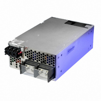
SWS600L-24
Manufacturer Part Number
SWS600L-24
Description
POWER SUPPLY 24V 27A SGL OUTPUT
Manufacturer
TDK Corporation
Series
SWSr
Type
Commercialr
Specifications of SWS600L-24
Power Supply Type
Switching (Closed Frame)
Voltage - Output
24V
Number Of Outputs
1
Power (watts)
600W
Applications
Commercial
Voltage - Input
85 ~ 265VAC
Mounting Type
Chassis Mount
1st Output
24 VDC @ 27A
Size / Dimension
7.48" L x 4.72" W x 2.4" H (190mm x 120mm x 61mm)
Power (watts) - Rated
648W
Operating Temperature
-20°C ~ 74°C
Efficiency
84%
Approvals
CSA, DENAN, EN, IEC, UL
Power Supply Output Type
Fixed
No. Of Outputs
1
Output Voltage
24V
Output Current
27A
Power Rating
648W
Input Voltage
85V AC To 265V AC / 120V DC To 350V DC
Brand/series
SWS Series
Configuration
Enclosed
Output
24 VDC @ 27 A
Power, Output
648 W
Primary Type
AC-DC
Special Features
Parallelable, PFC, Remote On/Off, Remote Sense
Voltage, Input
85 to 265/120 to 350 VAC/VDC
Voltage, Output
24 VDC
Input Frequency
47 to 63Hz
Screening Level
Commercial
Operating Temperature Min Deg. C
-20C
Mounting Style
Desktop
Lead Free Status / RoHS Status
Lead free / RoHS Compliant
3rd Output
-
2nd Output
-
4th Output
-
Lead Free Status / Rohs Status
RoHS Compliant part
Other names
285-1742
SWS600L24
SWS600L24
Available stocks
Company
Part Number
Manufacturer
Quantity
Price

Part Number:
SWS600L-24
Quantity:
119


10
SWS
Please pay extra attention to the wiring. Incorrect connection
will damage the power supply.
SWS600L
SWS1000L
① V.ADJ : Output voltage adjustment trimmer.
② ON : Output (Power on) indication LED
③ CN1, CN2, CN3 : Remote sensing, ON/OFF control signal,
④ : Protective earth (Frame ground), M4 screw.
⑤ AC input terminal L : Live line (Fuse in line), M4 screw.
⑥ AC input terminal N : Neutral line, M4 screw.
⑦ + : + Output terminal
⑧ - : - Output terminal
(The output voltage rises when a trimmer is turned clockwise.)
(The indicator turns on when the power supply output is in
normal operating condition.)
current balance signal, power fail alarm, auxiliary output,
output voltage external control signal. (Refer to 1-2.)
(SWS1000L: M4 screw x 2)
(SWS600L: M5 screw x 2 / SWS1000L:φ9hall, M4 tapped hall x 2)
(SWS600L: M5 screw x 2 / SWS1000L:φ9hall, M4 tapped hall x 2)
Front Panel Explanation
L
⑤
L
⑤
N
N
600L, 1000L
⑥
⑥
②
④
④
①
②
③
①
⑧
⑧
③
2. Terminal Explanation
⑦
⑦
CN1 and CN2 are same pin confi guration and function. They are
connected to each other in this power supply unit. When the pin
of CN1 side is shorted, the same function pins of CN2 side are
also shorted. Please note that the function cannot be separately
set with CN1 and CN2.
PIN HEADER
SOCKET HOUSING
TERMINAL PINS
HAND CRIMPING
TOOL
7
5
3
1
PART DESCRIPTION
9
7
5
3
1
9
7
5
3
1
CN1, CN2
CN1, CN2, CN3 Connector & Housing & Terminal Pin
CN3
CN1
CN2
CN3
C N1, C N 2 , C N 3 C o n n e c t o r p i n
Configuration and Function
10
10
8
6
4
2
8
6
4
2
8
6
4
2
Pin No
Pin No
10
1
2
3
4
5
6
7
8
9
1
2
3
4
5
6
7
8
Config-
Config-
uration
uration
S10B-PHDSS (CN1, CN2)
S8B-PHDSS (CN3)
PHDR-10VS (CN1, CN2)
PHDR-8VS (CN3)
SPHD-002T-P05 (AWG28~24)
SPHD-001T-P05 (AWG26~22)
YRS-620 (SPHD-002T-P0.5)
YC-610R (SPHD-001T-P0.5)
CNT2 REMOTE ON/OFF (2)
・All specifications are subject to change without notice.
CNT1
COM
COM
COM
TOG
ALM
+Vm
N.C.
AUX
-Vm
+S
PC
PV
G2
G2
G1
-S
+OUTPUT VOLTAGE MONITOR
+SENSING
-OUTPUT VOLTAGE MONITOR
-SENSING
NO CONNECTION
CURRENT BALANCE
ADJUSTMENT OF OUTPUT VOLTAGE
GROUND FOR PC AND PV SIGNAL
GROUND FOR CNT2
GROUND FOR PC AND PV SIGNAL
GROUND FOR PC AND PV SIGNAL
AUXILIARY OUTPUT (12V 0.1A)
REMOTE ON/OFF (1)
GROUND FOR AUX AND CNT1
GROUND FOR AUX AND CNT1
ALARM
ALARM GROUND
PART NAME
Function
Function
MANUFACT
J.S.T
J.S.T
J.S.T
J.S.T
Related parts for SWS600L-24
Image
Part Number
Description
Manufacturer
Datasheet
Request
R

Part Number:
Description:
POWER SUPPLY 60V 10A SGL OUTPUT
Manufacturer:
TDK Corporation

Part Number:
Description:
POWER SUPPLY 48V SGL OUTPUT
Manufacturer:
TDK Corporation
Datasheet:

Part Number:
Description:
POWER SUPPLY 12V 53A SGL OUTPUT
Manufacturer:
TDK Corporation
Datasheet:

Part Number:
Description:
POWER SUPPLY 60V 10A SGL OUTPUT
Manufacturer:
TDK Corporation
Datasheet:

Part Number:
Description:
POWER SUPPLY 15V 43A SGL OUTPUT
Manufacturer:
TDK Corporation
Datasheet:
Part Number:
Description:
POWER SUPPLY 5V 120A SGL OUTPUT
Manufacturer:
TDK Corporation
Datasheet:

Part Number:
Description:
POWER SUPPLY 3.3V 120A SGL OTPT
Manufacturer:
TDK Corporation
Datasheet:

Part Number:
Description:
POWER SUPPLY 36V 18A SGL OUTPUT
Manufacturer:
TDK Corporation
Datasheet:
Part Number:
Description:
AC-DC, 115-230VAC, Output 24V 27A, 648W
Manufacturer:
TDK Corporation

Part Number:
Description:
POWER SUPPLY, SWITCH MODE, 24V
Manufacturer:
TDK Corporation
Datasheet: