LTM8032IV#PBF Linear Technology, LTM8032IV#PBF Datasheet - Page 10
LTM8032IV#PBF
Manufacturer Part Number
LTM8032IV#PBF
Description
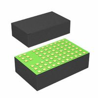
IC BUCK ADJ 2A 71LGA
Manufacturer
Linear Technology
Series
µModuler
Type
Point of Load (POL) Non-Isolatedr
Datasheet
1.LTM8032EVPBF.pdf
(20 pages)
Specifications of LTM8032IV#PBF
Design Resources
LTM8032 Spice Model
Output
0.8 ~ 10 V
Number Of Outputs
1
Power (watts)
20W
Mounting Type
Surface Mount
Voltage - Input
3.6 ~ 36 V
Package / Case
71-LGA
1st Output
0.8 ~ 10 VDC @ 2A
Size / Dimension
0.59" L x 0.35" W x 0.11" H (15mm x 9mm x 2.8mm)
Power (watts) - Rated
20W
Operating Temperature
-40°C ~ 125°C
Approvals
EN
Lead Free Status / RoHS Status
Lead free / RoHS Compliant
3rd Output
-
2nd Output
-
Available stocks
Company
Part Number
Manufacturer
Quantity
Price


APPLICATIONS INFORMATION
LTM8032
may have only a small fraction of their nominal capaci-
tance resulting in much higher output voltage ripple than
expected. Ceramic capacitors are also piezoelectric. In
Burst Mode operation, the LTM8032’s switching frequency
depends on the load current, and can excite a ceramic
capacitor at audio frequencies, generating audible noise.
Since the LTM8032 operates at a lower current limit during
Burst Mode operation, the noise is typically very quiet to a
casual ear. If this audible noise is unacceptable, use a high
performance electrolytic capacitor at the output. The input
capacitor can be a parallel combination of a 2.2μF ceramic
capacitor and a low cost electrolytic capacitor.
A fi nal precaution regarding ceramic capacitors concerns
the maximum input voltage rating of the LTM8032. A
ceramic input capacitor combined with trace or cable
inductance forms a high Q (under damped) tank circuit.
If the LTM8032 circuit is plugged into a live supply, the
input voltage can ring to twice its nominal value, possi-
bly exceeding the device’s rating. This situation is easily
avoided; see the Hot-Plugging Safely section.
Electromagnetic Compliance
The LTM8032 is compliant with the radiated emissions
requirements of EN55022 class B. Graphs of the LTM8032’s
EMC performance are given in the Typical Performance
Characteristics section. Further data, operating conditions
and test setup are detailed in an EMI Test report available
from Linear Technology.
Frequency Selection
The LTM8032 uses a constant frequency PWM architecture
that can be programmed to switch from 200kHz to 2.4MHz
by using a resistor tied from the RT pin to ground. Table 2
provides a list of R
frequencies.
Operating Frequency Trade-Offs
It is recommended that the user apply the optimal R
value given in Table 1 for the input and output operating
condition. System level or other considerations, however,
may necessitate another operating frequency. While the
LTM8032 is fl exible enough to accommodate a wide range
10
T
resistor values and their resultant
T
Table 2. Switching Frequency vs R
of operating frequencies, a haphazardly chosen one may
result in undesirable operation under certain operating or
fault conditions. A frequency that is too high can reduce
effi ciency, generate excessive heat or even damage the
LTM8032 if the output is overloaded or short-circuited.
A frequency that is too low can result in a fi nal design
that has too much output ripple or too large of an output
cap. The maximum frequency (and attendant R
which the LTM8032 should be allowed to switch is given
in Table 1 in the f
frequency (and R
given input condition is given in the f
There are additional conditions that must be satisfi ed if
the synchronization function is used. Please refer to the
Synchronization section for details.
BIAS Pin Considerations
The BIAS pin is used to provide drive power for the internal
power switching stage and operate internal circuitry. For
proper operation, it must be powered by at least 2.8V. If
the output voltage is programmed to be 2.8V or higher,
simply tie BIAS to AUX. If V
can be tied to V
cases, ensure that the maximum voltage at the BIAS pin
is both less than 25V and the sum of V
SWITCHING FREQUECNY (MHz)
0.2
0.3
0.4
0.5
0.6
0.7
0.8
0.9
1.0
1.2
1.4
1.5
1.8
2.2
2.4
2
IN
T
MAX
value) for optimal effi ciency over the
or some other voltage source. In all
column, while the recommended
OUT
T
Value
is less than 2.8V, BIAS
R
T
IN
VALUE (kΩ)
OPTIMAL
and BIAS is less
88.7
69.8
54.9
44.2
39.2
29.4
23.7
19.1
16.2
13.3
11.5
9.76
8.66
187
124
34
T
value) at
column.
8032fc
Related parts for LTM8032IV#PBF
Image
Part Number
Description
Manufacturer
Datasheet
Request
R

Part Number:
Description:
Ultralow Noise Emc Compliant 36v, 2a Dc/dc ?module
Manufacturer:
Linear Technology Corporation
Datasheet:

Part Number:
Description:
BOARD DEMO LTM8032
Manufacturer:
Linear Technology
Datasheet:

Part Number:
Description:
IC UMODULE DC/DC ULN 2A 71-LGA
Manufacturer:
Linear Technology
Datasheet:
Part Number:
Description:
IC BUCK ADJ 2A 71LGA
Manufacturer:
Linear Technology
Datasheet:
Part Number:
Description:
CD ROM LINEARVIEW DATASHEETS
Manufacturer:
Linear Technology
Part Number:
Description:
Standalone Linear Li-Ion Battery Charger with Thermal Regulation in ThinSOT
Manufacturer:
Linear Technology Corporation
Datasheet:
Part Number:
Description:
Low noise, high frequency, 8th order linear phase lowpass filter
Manufacturer:
Linear Technology Corporation
Datasheet:
Part Number:
Description:
Manufacturer:
Linear Technology Corporation
Datasheet:
Part Number:
Description:
Manufacturer:
Linear Technology Corporation
Datasheet:
Part Number:
Description:
Manufacturer:
Linear Technology Corporation
Datasheet:
Part Number:
Description:
Manufacturer:
Linear Technology Corporation
Datasheet:
Part Number:
Description:
Manufacturer:
Linear Technology Corporation
Datasheet:
Part Number:
Description:
Manufacturer:
Linear Technology Corporation
Datasheet:
Part Number:
Description:
Manufacturer:
Linear Technology Corporation
Datasheet:
Part Number:
Description:
Dual and Quad, JFET Input Precision High Speed Op Amps
Manufacturer:
Linear Technology Corporation
Datasheet: