GL100MN0MP Sharp Microelectronics, GL100MN0MP Datasheet - Page 6
GL100MN0MP
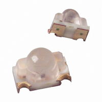
Manufacturer Part Number
GL100MN0MP
Description
EMITTER IR 940NM GP 3.0MW SMD
Manufacturer
Sharp Microelectronics
Datasheet
1.GL100MN0MP.pdf
(11 pages)
Specifications of GL100MN0MP
Current - Dc Forward (if)
50mA
Wavelength
940nm
Voltage - Forward (vf) Typ
1.2V
Viewing Angle
20°
Orientation
Universal
Mounting Type
Surface Mount
Package / Case
Non-Standard SMD
Lead Free Status / RoHS Status
Lead free / RoHS Compliant
Radiant Intensity (ie) Min @ If
-
Other names
425-1022-2


■ Design Considerations
1. Allow for natural degradation of the LED as a result of long continuous operation. This part will have 50% deg-
2. This product is not designed to be electromagnetic- and ionized-particle-radiation resistant.
■ Manufacturing Guidelines
1. Sharp recommends soldering no more than once when using solder reflow methods.
2. When using solder reflow methods, follow the Reflow Soldering Temperature Profile shown in Fig. 10. Sharp
3. If using an infrared lamp to preheat the parts, such heat sources may cause localized high temperatures in the
4. If hand soldering, use temperatures ≤ 260° for ≤ 3 seconds. Do not dip-solder or VPS-solder this part.
5. Do not subject the package to excessive mechanical force during soldering as it may cause deformation or
Fig. 10 Reflow Soldering Temperature Profile
240°C MAX.
165°C MAX.
1. Confirm this device's resistance to process chemicals before use, as certain process chemicals may affect the
2. Solvent cleaning: Solvent temperature should be 45°C or below. Immersion time should be 3 minutes or less.
3. Ultrasonic cleaning: The effect upon devices varies due to cleaning bath size, ultrasonic power output, cleaning
4. Recommended solvent materials: Ethyl alcohol, Methyl alcohol, and Isopropyl alcohol.
Design Guidelines
Soldering Instructions
Cleaning Instructions
radation in output after 5 years of continuous use.
recommends checking the process to make sure these parameters are not exceeded; exceeding these param-
eters can cause substrate bending or other mechanical stresses leading to debonding of the internal gold wires,
or other similar failure modes.
part's resin. Be sure to keep the temperature profile within the guidelines shown in Fig. 10.
defects in plated connections. Internal connections may be severed due to mechanical force placed on the pack-
age due to the PCB flexing during the soldering process.
optical characteristics.
time, PCB size and device mounting circumstances. Sharp recommends testing using actual production condi-
tions to confirm the harmlessness of the ultrasonic cleaning methods.
200°C
25°C
1 ~ 4°C/s
120 s MAX.
1 ~ 4°C/s
90 s MAX.
10 s MAX.
60 s MAX.
1 ~ 4°C/s
6
GL100MN0MPx
Sheet No.: D1-A00601EN
Related parts for GL100MN0MP
Image
Part Number
Description
Manufacturer
Datasheet
Request
R

Part Number:
Description:
Photo Sensors-Diffuse Mode
Manufacturer:
PEPPERL & FUCHS

Part Number:
Description:
IC FLASH 32MBIT 110NS 56SSOP
Manufacturer:
Sharp Microelectronics
Datasheet:

Part Number:
Description:
IC FLASH 16MBIT 100NS 56TSOP
Manufacturer:
Sharp Microelectronics
Datasheet:

Part Number:
Description:
IC FLASH 64MBIT 120NS 56TSOP
Manufacturer:
Sharp Microelectronics
Datasheet:

Part Number:
Description:
IC FLASH 16MBIT 90NS 48TSOP
Manufacturer:
Sharp Microelectronics
Datasheet:
Part Number:
Description:
IC SRAM 16KBIT 100NS 24DIP
Manufacturer:
Sharp Microelectronics
Datasheet:
Part Number:
Description:
IC SRAM 16KBIT 100NS 24SOP
Manufacturer:
Sharp Microelectronics
Datasheet:
Part Number:
Description:
IC SRAM 64KBIT 100NS 28DIP
Manufacturer:
Sharp Microelectronics
Datasheet:
Part Number:
Description:
IC SRAM 64KBIT 100NS 28SOP
Manufacturer:
Sharp Microelectronics
Datasheet:
Part Number:
Description:
IC SRAM 64KBIT 100NS 28SOP
Manufacturer:
Sharp Microelectronics
Datasheet:
Part Number:
Description:
IC SRAM 256KBIT 70NS 28DIP
Manufacturer:
Sharp Microelectronics
Datasheet:
Part Number:
Description:
IC FLASH 8MBIT 90NS 48TSOP
Manufacturer:
Sharp Microelectronics
Datasheet:
Part Number:
Description:
IC FLASH 8MBIT 85NS 40TSOP
Manufacturer:
Sharp Microelectronics
Datasheet:
Part Number:
Description:
IC FLASH 8MBIT 85NS 40TSOP
Manufacturer:
Sharp Microelectronics
Datasheet:
Part Number:
Description:
IC FLASH 16MBIT 90NS 48TSOP
Manufacturer:
Sharp Microelectronics
Datasheet: