KP-F1 Panduit Corp, KP-F1 Datasheet - Page 776
KP-F1
Manufacturer Part Number
KP-F1
Description
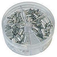
KIT FERRULE NONINS AWG22-14
Manufacturer
Panduit Corp
Series
Pan-Term®r
Type
Ferrule kitr
Datasheet
1.KP-FSD1.pdf
(1040 pages)
Specifications of KP-F1
Kit Type
Ferrule - Wire End
Values
370 pcs - Assorted Non-Insulated 22 ~ 14 AWG Ferrules
Kit Contents
500 Pieces Of F75-6, 400 Pieces Of F76-6 & F77-6, 300 Pieces Of F78-7, 200 Pieces Of F80-7
Lead Free Status / Rohs Status
Lead free / RoHS Compliant


Management
Identification
Accessories
Connectors
Connectors
& Write-On
Protection
Grounding
Pre-Printed
Cable Ties
Terminals
Permanent
Solutions
Overview
Steel Ties
Lockout/
& Safety
D2.154
Stainless
Raceway
Abrasion
Labeling
Systems
Markers
Tagout
System
Surface
Wiring
Power
Labels
Index
Cable
Cable
Duct
E5.
B1.
B2.
B3.
C1.
C2.
C3.
C4.
D1.
D2.
D3.
E1.
E2.
E3.
E4.
A.
F.
For Use with Aluminum or Copper Code Conductors
Type PCSBMT
• Flexible design – can be used as a tap, splice, or dead
• Body made from high strength, extruded aluminum alloy to provide
• Two isolated mounting holes at either end of connector
• Insulated with clear PVC to eliminate the need for taping and
Part Number
PCSBMT2/0-4-3Y
PCSBMT2/0-6-2Y
PCSBMT2/0-8-2Y
PCSBMT2/0-10-2Y
PCSBMT2/0-12-1Y
PCSBMT250-4-2Y
PCSBMT250-6-2Y
PCSBMT250-8-2Y
PCSBMT250-10-2Y
PCSBMT250-12-1Y
PCSBMT350-4-2Y
PCSBMT350-6-2Y
PCSBMT350-8-2Y
PCSBMT350-10-1Y
PCSBMT350-12-1Y
PCSBMT600-4-2Y
PCSBMT600-6-2Y
PCSBMT600-8-2Y
PCSBMT600-10-1Y
PCSBMT600-12-1Y
end connector
premium electrical and mechanical performance
facilitate direct mounting using 1/4" bolts
allow for visual inspection of the complete conductor insertion
Multi-Tap Connector with Clear Insulation, Double-Sided, with Mounting Holes
250 kcmil – #10 AWG STR
350 kcmil – #10 AWG STR
600 kcmil – #6 AWG STR
Conductor Size Range
2/0 – #14 AWG STR,
#10 – #14 AWG SOL
No. of
Ports
10
12
10
12
10
12
10
12
4
6
8
4
6
8
4
6
8
4
6
8
ELECTRICAL SOLUTIONS
11.41
13.29
10.17
12.17
14.17
10.41
12.97
15.53
18.09
4.20
5.55
6.89
8.24
9.58
5.78
7.66
9.53
6.17
8.17
7.84
L
1.56
1.56
1.56
1.56
1.56
2.63
2.63
2.63
2.63
2.63
3.00
3.00
3.00
3.00
3.00
3.00
3.00
3.00
3.00
3.00
Figure Dimensions (In.)
W
W
H
• Each port pre-filled with oxide inhibiting joint compound seals out
• Wide wire range-taking capability minimizes inventory requirements
• Dual-sided entry allows offset and opposite entry for primary and
• Plated steel or aluminum set screw provides high strength, durable
• UL Listed and CSA Certified for use up to 600 V and temperature
air and moisture to deter surface oxidation
secondary conductors
electrical contact between conductor and connector
rated 90°C
1.50
1.50
1.50
1.50
1.50
2.26
2.26
2.26
2.26
2.26
2.63
2.63
2.63
2.63
2.63
2.88
2.88
2.88
2.88
2.88
H
S
M
L
0.67
0.67
0.67
0.67
0.67
0.94
0.94
0.94
0.94
0.94
1.00
1.00
1.00
1.00
1.00
1.28
1.28
1.28
1.28
1.28
S
10.57
12.45
11.25
13.25
11.78
14.34
16.90
3.61
4.96
6.30
7.65
8.99
4.94
6.82
8.69
5.25
7.25
9.25
6.65
9.22
M
Mounting Hole
Size
(In.)
1/4
1/4
1/4
1/4
1/4
1/4
1/4
1/4
1/4
1/4
1/4
1/4
1/4
1/4
1/4
1/4
1/4
1/4
1/4
1/4
Prime items appear in BOLD.
Hex Key
23/32
23/32
23/32
23/32
23/32
15/16
15/16
15/16
15/16
15/16
Size
(In.)
1/2
1/2
1/2
1/2
1/2
7/8
7/8
7/8
7/8
7/8
Pkg.
Std.
Qty.
3
2
2
2
1
2
2
2
2
1
2
2
2
1
1
2
2
2
1
1