KP-F1 Panduit Corp, KP-F1 Datasheet - Page 688
KP-F1
Manufacturer Part Number
KP-F1
Description
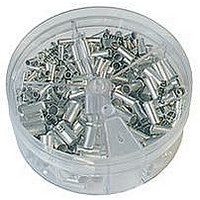
KIT FERRULE NONINS AWG22-14
Manufacturer
Panduit Corp
Series
Pan-Term®r
Type
Ferrule kitr
Datasheet
1.KP-FSD1.pdf
(1040 pages)
Specifications of KP-F1
Kit Type
Ferrule - Wire End
Values
370 pcs - Assorted Non-Insulated 22 ~ 14 AWG Ferrules
Kit Contents
500 Pieces Of F75-6, 400 Pieces Of F76-6 & F77-6, 300 Pieces Of F78-7, 200 Pieces Of F80-7
Lead Free Status / Rohs Status
Lead free / RoHS Compliant


Management
Identification
Accessories
Connectors
Connectors
& Write-On
Protection
Grounding
Pre-Printed
Cable Ties
Terminals
Permanent
Solutions
Overview
Steel Ties
Lockout/
& Safety
Stainless
Raceway
Abrasion
Labeling
Systems
Markers
Tagout
System
Surface
Wiring
Power
Labels
Index
Cable
Cable
D2.66
Duct
E5.
B1.
B2.
B3.
C1.
C2.
C3.
C4.
D1.
D2.
D3.
E1.
E2.
E3.
E4.
A.
F.
For Use with Flexible, Extra-Flexible, and Code Stranded Copper Conductors
Type LCAX
• Can be used with code conductor and flex conductor class: G, H, I,
• Generously beveled wire entry prevents bent back strands when
• Color-coded barrels marked with Panduit and specified competitor
‡See pages D3.70 – D3.73 for tool and die information.
*Not UL Listed or CSA Certified with Class K flex conductor when crimped with Burndy tools.
**Consult cable manufacturer for voltage stress relief instructions with applications greater than 2000 V.
Part Number
LCAX8-10-L
LCAX8-14-L
LCAX8-56-L
LCAX8-38-L
LCAX6-10-L
LCAX6-14-L
LCAX6-56-L
LCAX6-38-L
LCAX4-10-L
LCAX4-14-L
LCAX4-56-L
LCAX4-38-L
LCAX2-10-E*
LCAX2-14-E*
LCAX2-56-E*
LCAX2-38-E*
LCAX2-12-E*
LCAX1-10-X
LCAX1-14-X
LCAX1-56-X
LCAX1-38-X
LCAX1-12-X
K, M and Diesel Locomotive
inserting conductor into barrel
die index numbers for proper crimp die selection
Order number of pieces required, in multiples of Standard Package Quantity.
Flex Conductor, One-Hole, Standard Barrel with Window Lug
G, H, I, K, M
#8 AWG
#6 AWG
#4 AWG
#2 AWG
#1 AWG
Flex Conductor Size
Class
Locomotive
#5, #4, #3
#8 AWG
#6 AWG
#2 AWG
#1 AWG
Diesel
AWG
Conductor
#8 AWG
#6 AWG
#4 AWG
#2 AWG
#1 AWG
Code
Size
Stud
Hole
Size
5/16
5/16
5/16
5/16
5/16
(In.)
#10
#10
#10
#10
#10
ELECTRICAL SOLUTIONS
1/4
3/8
1/4
3/8
1/4
3/8
1/4
3/8
1/2
1/4
3/8
1/2
0.41 0.42 0.08 1.11
0.48 0.42 0.07 1.20
0.56 0.42 0.05 1.32
0.60 0.42 0.05 1.42
0.45 0.48 0.09 1.19
0.48 0.48 0.08 1.28
0.56 0.48 0.07 1.40
0.62 0.48 0.06 1.50
0.55 0.53 0.09 1.26
0.55 0.53 0.09 1.35
0.55 0.53 0.09 1.47
0.62 0.53 0.07 1.57
0.70 0.59 0.11 1.40
0.70 0.59 0.11 1.50
0.70 0.59 0.11 1.63
0.70 0.59 0.11 1.70
0.75 0.59 0.09 1.94
0.76 0.66 0.12 1.50
0.76 0.66 0.12 1.67
0.76 0.66 0.12 1.72
0.76 0.66 0.12 1.80
0.80 0.66 0.12 2.03
Figure Dimensions
W
B
(In.)
• Inspection window to visually assure full conductor insertion
• Tin-plated to inhibit corrosion
• UL Listed and CSA Certified to 35 KV** and temperature rated to
• American Bureau of Shipping approved
T
W
90°C when crimped with Panduit and specified competitor
crimping tools and dies
T
INSPECTION
L
WINDOW
Panduit
Brown
Brown
Brown
Brown
Brown
Green
Green
Green
Green
Green
Color
Code
Blue
Blue
Blue
Blue
Gray
Gray
Gray
Gray
Red
Red
Red
Red
L
Die Index
Panduit
B
No.‡
P21
P21
P21
P21
P24
P24
P24
P24
P29
P29
P29
P29
P33
P33
P33
P33
P33
P37
P37
P37
P37
P37
Burndy
Index
No.‡
Die
49
49
49
49
10
10
10
10
10
11
11
11
11
11
7
7
7
7
8
8
8
8
Prime items appear in BOLD.
Index
No.‡
T&B
Die
21
21
21
21
24
24
24
24
29
29
29
29
33
33
33
33
33
37
37
37
37
37
Wire Strip
Length
11/16
11/16
11/16
11/16
11/16
(In.)
9/16
9/16
9/16
9/16
1/2
1/2
1/2
1/2
5/8
5/8
5/8
5/8
3/4
3/4
3/4
3/4
3/4
Pkg.
Std.
Qty.
50
50
50
50
50
50
50
50
50
50
50
50
20
20
20
20
20
10
10
10
10
10