KP-F1 Panduit Corp, KP-F1 Datasheet - Page 479
KP-F1
Manufacturer Part Number
KP-F1
Description
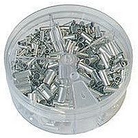
KIT FERRULE NONINS AWG22-14
Manufacturer
Panduit Corp
Series
Pan-Term®r
Type
Ferrule kitr
Datasheet
1.KP-FSD1.pdf
(1040 pages)
Specifications of KP-F1
Kit Type
Ferrule - Wire End
Values
370 pcs - Assorted Non-Insulated 22 ~ 14 AWG Ferrules
Kit Contents
500 Pieces Of F75-6, 400 Pieces Of F76-6 & F77-6, 300 Pieces Of F78-7, 200 Pieces Of F80-7
Lead Free Status / Rohs Status
Lead free / RoHS Compliant


Type PNF-R
• Ring tongue design assures a secure connection in high vibration
• Metal insulation grip sleeve crimps to wire insulation, providing
• Internal barrel serrations assure good wire contact and maximum
applications
protection to the crimp joint during high vibration applications
tensile strength
C
L
Ring Terminal, Nylon Insulated – Funnel Entry
W
**Bulk packaging may be available, contact Panduit Customer Service for additional information.
^For military specification cross reference see page D1.96.
‡UL and CSA approved tooling/product combinations. For crimping tool information, see pages D1.83, D1.84,
D1.86 and D1.88.
Part Number
PNF18-4R-C
PNF18-6RN-C^
PNF18-6R-C^
PNF18-8R-C^
PNF18-10R-C^
PNF18-14R-C^
PNF18-56R-C^
PNF18-38R-C^
PNF14-4R-C^
PNF14-6RN-C^
PNF14-6R-C^
PNF14-8R-C^
PNF14-10R-C^
PNF14-14R-C^
PNF14-56R-C^
PNF14-38R-L^
PNF10-6R-L^
PNF10-8R-L^
PNF10-10R-L^
PNF10-14R-L^
PNF10-56R-L^
PNF10-38R-L^
For technical assistance in the U.S., call 866-405-6654 (outside the U.S., see inside back cover for directory)
22 – 18
16 – 14
Range
12 –10
ELECTRICAL SOLUTIONS
AWG
AWG
AWG
Wire
Yellow
Color
Code
Blue
Red
• UL Flammability UL 94V-2/HB, maximum insulation temperature
• UL and CSA rated up to 600 V per UL 486A/B
Thickness
221°F (105°C)
Stock
(In.)
0.03
0.03
0.03
0.03
0.03
0.03
0.03
0.03
0.03
0.03
0.03
0.03
0.03
0.03
0.03
0.03
0.04
0.04
0.04
0.04
0.04
0.04
0.136
0.136
0.136
0.136
0.136
0.136
0.136 5/16" 1.08
0.136
0.162
0.162
0.162
0.162
0.162
0.162
0.162 5/16" 1.06
0.162
0.225
0.225
0.225
0.225
0.225 5/16" 1.21
0.225
Max.
(In.)
Ins.
Stud
Size
#10
1/4"
3/8"
#10
1/4"
3/8"
#10
1/4"
3/8"
#4
#6
#6
#8
#4
#6
#6
#8
#6
#8
Figure Dimensions
0.77
0.76
0.77
0.87
0.87
1.08
1.16
0.78
0.78
0.87
0.87
0.85
1.06
1.14
1.06
1.06
1.06
1.21
1.29
L
(In.)
0.25
0.22
0.25
0.31
0.32
0.46
0.46
0.53
0.25
0.25
0.31
0.31
0.31
0.46
0.46
0.53
0.37
0.37
0.37
0.52
0.52
0.58
W
0.20
0.18
0.20
0.24
0.25
0.38
0.39
0.41
0.18
0.18
0.24
0.25
0.29
0.40
0.40
0.45
0.31
0.31
0.31
0.38
0.38
0.43
C
Recommended
Installation
CT-600-A‡,
CT-600-A‡,
CT-600-A‡,
CT-100A‡,
CT-100A‡,
CT-100A‡,
CT-1550‡,
CT-1551‡,
CT-1550‡,
CT-1551‡,
CT-1550‡,
CT-1551‡,
CT-2500‡
CT-2500‡
CT-2500‡
Tool
Qty.**
Pkg.
Std.
100
100
100
100
100
100
100
100
100
100
100
100
100
100
100
50
50
50
50
50
50
50
Ctn.
Std.
Qty.
500
500
500
500
500
500
500
500
500
500
500
500
500
500
500
500
500
500
500
500
500
500
D1.7
Management
Identification
Accessories
Connectors
Connectors
Grounding
Pre-Printed
& Write-On
Protection
Permanent
Solutions
Cable Ties
Terminals
Lockout/
Overview
Steel Ties
& Safety
Stainless
Raceway
Abrasion
Labeling
Systems
Surface
Markers
Tagout
System
Wiring
Labels
Power
Cable
Cable
Index
Duct
E5.
B1.
B2.
B3.
D1.
D2.
D3.
C1.
C2.
C3.
C4.
E1.
E2.
E3.
E4.
A.
F.