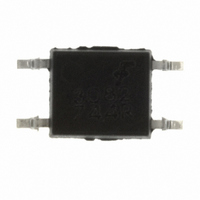
FODM3082 Fairchild Optoelectronics Group, FODM3082 Datasheet - Page 7

FODM3082
Manufacturer Part Number
FODM3082
Description
IC TRIAC ZERO X 800V 10MA 4-MFP
Manufacturer
Fairchild Optoelectronics Group
Datasheet
1.FODM3082.pdf
(13 pages)
Specifications of FODM3082
Voltage - Isolation
3750Vrms
Number Of Channels
1
Voltage - Off State
800V
Output Type
AC, Triac, Zero Cross
Current - Gate Trigger (igt) (max)
10mA
Current - Hold (ih)
300µA
Current - Dc Forward (if)
60mA
Current - Output / Channel
70mA
Mounting Type
Surface Mount
Package / Case
4-MFP
Lead Free Status / RoHS Status
Lead free / RoHS Compliant
©2006 Fairchild Semiconductor Corporation
FODM3062, FODM3063, FODM3082, FODM3083 Rev. 1.0.9
V
Determining the Power Rating of the Series Resistors Used in a Zero-Cross
Opto-TRIAC Driver Application
The following will present the calculations for
determining the power dissipation of the current
limiting resistors found in an opto-TRIAC driver
interface.
Figure 10 shows a typical circuit to drive a sensitive
gate four quadrant power TRIAC. This figure provides
typical resistor values for a zero line cross detecting
opto-TRIAC when operated from a mains voltage of
20V to 240V. The wattage rating for each resistor is
not given because their dissipation is dependent upon
characteristics of the power TRIAC being driven.
Recall that the opto-TRIAC is used to trigger a four
quadrant power TRIAC. Please note that these opto-
TRIACs
“snubberless” three quadrant power TRIACs.
Under normal operation, the opto-TRIAC will fire when
the mains voltage is lower than the minimum inhibit
trigger voltage, and the LED is driven at a current
greater than the maximum LED trigger current. As an
example for the FODM3063, the LED trigger current
should be greater than 5mA, and the mains voltage is
less than 10V peak. The inhibit voltage has a typical
range of 10V minimum and 20V maximum. This
means that if a sufficient LED current is flowing when
the mains voltage is less than 10V, the device will fire.
If a trigger appears between 10V and 20V, the device
may fire. If the trigger occurs after the mains voltage
has reached 20Vpeak, the device will not fire.
CC
*
For highly inductive loads (power factor < 0.5), change this value to 360 ohms.
R
in
are
1
2
not
FODM3062
FODM3063
FODM3082
FODM3083
recommended
4
3
330
Figure 10. Hot-Line Switching Application Circuit
360 Ω
for
driving
39*
0.01
LOAD
7
The power dissipated from resistors placed in series
with the opto-TRIAC and the gate of the power TRIAC
is much smaller than one would expect. These current
handling components only conduct current when the
mains voltage is less than the maximum inhibit
voltage. If the opto-TRIAC is triggered when the mains
voltage is greater than the inhibit voltage, only the
TRIAC leakage current will flow. The power dissipation
in a 360Ω resistor shown in Figure 10 is the product of
the resistance (360Ω) times the square of the current
sum of main TRIAC’s gate current plus the current
flowing gate to the MT2 resistor connection (330Ω).
This power calculation is further modified by the duty
factor of the duration for this current flow. The duty
factor is the ratio of the turn-on time of the main TRIAC
to the sine of the single cycle time. Assuming a main
TRIAC turn-on time of 50µs and a 60Hz mains
voltage, the duty cycle is approximately 0.6%.
The opto-TRIAC only conducts current while triggering
the main TRIAC. Once the main TRIAC fires, its on-
state voltage is typically lower than the on-state
sustaining voltage of the opto-TRIAC. Thus, once the
main TRIAC fires, the opto-TRIAC is often shunted off.
This situation results in very low power dissipation for
both the 360Ω and 330Ω resistors, when driving a
traditional four quadrant power TRIAC.
If a three quadrant “snubberless” TRIAC is driven by
the opto-TRIAC, the calculations are different. When
the main power TRIAC is driving a high power factor
(resistive) load, it shuts off during the fourth quadrant.
HOT
NEUTRAL
240 VAC
is required. In this circuit the “hot” side of the line is
switched and the load connected to the cold or neutral
side. The load may be connected to either the neutral or
hot line.
part, 5mA for the FODM3063/83 and 10mA for the
FODM3062/82. The 39Ω resistor and 0.01µF capacitor are
for snubbing of the triac and may or may not be necessary
depending upon the particular triac and load used.
Typical circuit for use when hot line switching of 240VAC
R
in
is calculated so that I
F
is equal to the rated I
www.fairchildsemi.com
FT
of the


