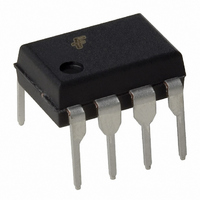
6N138V Fairchild Optoelectronics Group, 6N138V Datasheet

6N138V
Specifications of 6N138V
Related parts for 6N138V
6N138V Summary of contents
Page 1
... Low current – 0.5mA Superior CTR-2000% Superior CMR-10kV/µs CTR guaranteed 0–70°C U.L. recognized (File # E90700) VDE recognized (File # 120915) Ordering option V, e.g., 6N138V Dual Channel – HCPL2730, HCPL2731 Applications Digital logic ground isolation Telephone ring detector EIA-RS-232C line receiver High common mode noise line receiver µ ...
Page 2
Absolute Maximum Ratings Stresses exceeding the absolute maximum ratings may damage the device. The device may not function or be operable above the recommended operating conditions and stressing the parts to these levels is not recommended. In addition, extended exposure ...
Page 3
Electrical Characteristics Individual Component Characteristics Symbol Parameter EMITTER V Input Forward Voltage F BV Input Reverse R Breakdown Voltage Temperature F A Coefficient of Forward Voltage DETECTOR I Logic HIGH Output OH Current I Logic LOW supply ...
Page 4
Electrical Characteristics Switching Characteristics (V Symbol Parameter T Propagation Delay R PHL Time to Logic (2) LOW (Fig. 24) R Each Channel Propagation Delay R PLH Time to Logic (2) HIGH (Fig. 24 ...
Page 5
Electrical Characteristics Isolation Characteristics Symbol Characteristics I Input-Output Insulation Leakage I-O (4) Current V Withstand Insulation Test ISO (4) Voltage R Resistance (Input to Output) I-O C Capacitance (Input to Output) I-O I Input-Input Insulation Leakage I-I (6) Current R ...
Page 6
Electrical Characteristics Current Limiting Resistor Calculations R (Non-Invert – V – DD1 (Invert – V – DD1 OH1 ...
Page 7
Typical Performance Curves Fig. 4 LED Forward Current vs. Forward Voltage 100 85˚ 70˚C A 0.1 0. 25˚ 0˚C A 0.001 1.0 1.1 1.2 1.3 FORWARD VOLTAGE - ...
Page 8
Typical Performance Curves Fig. 10 Current Transfer Ratio vs. Base-Emitter Resistance (6N138 / 6N139 Only) 1600 1400 1200 1000 800 600 400 200 BASE RESISTANCE (k BE Fig. 12 Output Current vs Output Voltage (6N138 ...
Page 9
Typical Performance Curves Fig. 16 Logic Low Supply Current vs. Input Diode Forward Current (6N138 / 6N139 Only) 4.0 3.5 3.0 2 2.0 1.5 1.0 0.5 0 FORWARD CURRENT (mA) F Fig. ...
Page 10
Typical Performance Curves Fig. 22 Propagation Delay vs. Temperature (6N138 / 6N139 Only) 50 HCPL2730 : I = 1 HCPL2731 : I = 0 (HCPL2731) PLH ...
Page 11
Test Circuits Noise Shield 1 Pulse Generator 5ns 10% D. < 100ns 3 I Monitor Test Circuit for 6N138, 6N139 I F ...
Page 12
Package Dimensions Through Hole PIN 1 ID 0.270 (6.86) 0.250 (6.35 0.390 (9.91) 0.370 (9.40) 0.070 (1.78) 0.045 (1.14) 0.200 (5.08) 0.020 (0.51) MIN 0.140 (3.55) 0.154 (3.90) 0.120 (3.05) 0.022 (0.56) ...
Page 13
... Standard Through Hole Device, 50 pcs per tube 6N138S Surface Mount Lead Bend 6N138SD Surface Mount; Tape and reel 6N138W 0.4" Lead Spacing 6N138V VDE0884 6N138WV VDE0884; 0.4” lead spacing 6N138SV VDE0884; surface mount 6N138SDV VDE0884; surface mount; tape and reel ...
Page 14
Tape Specifications 4.90 0.20 0.30 13.2 0.2 0.1 MAX User Direction of Feed Reflow Profile 300 250 200 150 100 ©2005 Fairchild Semiconductor Corporation 6N138, 5N139, NCPL2730, HCPL2731 Rev. 1.0.5 12.0 0.1 4.0 0.1 4.0 0.1 0.05 10.30 0.20 225C ...
Page 15
TRADEMARKS The following includes registered and unregistered trademarks and service marks, owned by Fairchild Semiconductor and/or its global subsidiaries, and is not intended exhaustive list of all such trademarks. Build it Now™ CorePLUS™ CorePOWER™ CROSSVOLT™ CTL™ Current ...


