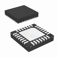
ISL62884CIRTZ Intersil, ISL62884CIRTZ Datasheet - Page 19

ISL62884CIRTZ
Manufacturer Part Number
ISL62884CIRTZ
Description
IC REG PWM SGL PHASE 28TQFN
Manufacturer
Intersil
Datasheet
1.ISL62884CHRTZ.pdf
(30 pages)
Specifications of ISL62884CIRTZ
Applications
Controller, Intel IMVP-6
Voltage - Input
4.5 ~ 25 V
Number Of Outputs
1
Voltage - Output
0.0125 ~ 1.5 V
Operating Temperature
-40°C ~ 100°C
Mounting Type
Surface Mount
Package / Case
28-VQFN
Lead Free Status / RoHS Status
Lead free / RoHS Compliant
Available stocks
Company
Part Number
Manufacturer
Quantity
Price
Part Number:
ISL62884CIRTZ
Manufacturer:
NA
Quantity:
20 000
C
constant. It usually takes the parallel of two (or more)
capacitors to get the desired value. Figure 15 shows
that two capacitors C
Resistor R
ring back. At steady state, C
desired C
the effective capacitance is less because R
the impedance of the C
explains, V
effect will reduce the V
pronounced when C
also more pronounced when R
presence of R
C
greater than 2200pF. R
C
through tuning the load transient response waveforms
on an actual board.
Resistor Current-Sensing Network
FIGURE 15. OPTIONAL CIRCUITS FOR RING BACK
FIGURE 16. RESISTOR CURRENT-SENSING NETWORK
n
n.2
n.1
is the capacitor used to match the inductor time
, C
is too small. It is recommended to keep C
Rntcs
Rntc
n.2
RSEN
DCR
n
n
PHASE
and R
L
Io
o
capacitance. At the beginning of i
is an optional component to reduce the V
REDUCTION
tends to dip when C
Rp
n
increases the ripple of the V
n
OPTIONAL
values should be determined
RSUM
n.1
n.1
Cn.1
o
n
n.1
is much larger than C
Rn
ring back. This effect is more
and C
19
value usually is a few ohms.
Vcn
branch. As Figure 12
n.1
n
n.2
is bigger. However, the
OPTIONAL
+ C
n
Rip Cip
Cn
is too small, and this
Cn.2
are in parallel.
+
Ri
-
n.2
Ri
Vcn
provides the
ISUM+
ISUM+
ISUM-
ISUM-
n
n
increases
o
n.2
signal if
change,
n.2
. It is
ISL62884C
o
Figure 16 shows the resistor current-sensing network.
The inductor has a series current-sensing resistor R
R
capture the inductor current information. The R
the sensed information to capacitor C
form a a filter for noise attenuation. Equations 12
through 14 gives V
Transfer function A
Current-sensing resistor R
significant variation over-temperature, so there is no
need for the NTC network.
The recommended values are R
C
Overcurrent Protection
Referring to Equation 1 and Figures 9, 10 and 16, resistor
R
internal OCP threshold. It is recommended to design
I
For example, the OCP threshold is 60µA. We will design
I
of the full load current.
For inductor DCR sensing, Equation 15 gives the DC
relationship of V
Substitution of Equation 15 into Equation 1 gives
Equation 16:
Therefore:
Substitution of Equation 7 and application of the OCP
condition in Equation 17 gives Equation 18:
where I
corresponding droop current. For example, given
R
DCR = 19.7mΩ, I
Equation 18 gives R
For resistor sensing, Equation 19 gives the DC
relationship of V
V
I
V
V
R
A
ω
droop
droop
droop
R
sum
n
i
sum
Cn
Cn
Cn
Rsen
i
Rsen
i
sets the droop current I
=
= 5600pF.
=
s ( )
=
=
----------------------------------------------------------------------------------------------------------------- -
⎛
⎜
⎝
--------------------------------------------------------------------- -
(
and is connected to the R
(
----------------------------------------------------
= 1.82kΩ, R
s ( )
R
=
2
to be 50µA at full load, so the OCP trip level is 1.2x
R
without using the R
⎛
⎜
⎝
R
R
=
=
----------------------------------------- -
R
2R
ntcnet
omax
×
ntcs
ntcs
sen
---- -
R
2
---------------------------- -
R
ntcnet
R
=
(
----------------------------------------------------
i
ntcnet
R
R
sum
sen
×
R
×
---------------------- -
1
ntcs
ntcs
+
+
----------------------------------------- -
R
ntcnet
+
I
1
+
R
R
is the full load current, I
o
ntcnet
×
×
1
------------ -
ω
+
R
ntc
ntc
I
R
+
+
sns
C
×
o
s
R
sum
cn
cn
ntcnet
R
s ( )
R
n
DCR
)
sum
omax
+
p
(s) and I
ntc
ntc
×
(s) and I
Rsen
Cn
+
R
)
= 11kΩ, R
×
R
i
R
×
p
)
= 3.01kΩ.
×
+
p
A
(s) expressions:
sum
×
×
I
droop
+
Rsen
DCR
R
= 5A and I
(s) always has unity gain at DC.
I
R
o
p
R
p
sum
×
sen
comp
×
droop
⎞
⎟
⎠
s ( )
o
DCR
o
DCR
×
(s).
(s).
⎞
⎟
⎠
ntcs
I
value will not have
×
o
sen
. Table 3 shows the
I
sum
resistor.
×
droopmax
×
I
= 2.61kΩ, R
o
I
droopmax
omax
pad to accurately
= 1kΩ and
droopmax
n
. R
sum
= 50µA,
ntc
March 16, 2010
and C
sum
is the
= 10kΩ,
(EQ. 12)
(EQ. 13)
(EQ. 14)
(EQ. 15)
(EQ. 16)
(EQ. 17)
(EQ. 18)
(EQ. 19)
FN7591.0
feeds
sen
n
.


