ADT7463ARQZ ON Semiconductor, ADT7463ARQZ Datasheet - Page 49
ADT7463ARQZ
Manufacturer Part Number
ADT7463ARQZ
Description
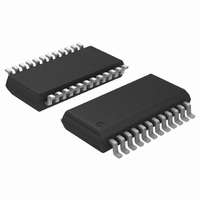
IC REMOTE THERMAL CTRLR 24-QSOP
Manufacturer
ON Semiconductor
Series
dBCool®r
Datasheet
1.ADT7463ARQZ-REEL.pdf
(52 pages)
Specifications of ADT7463ARQZ
Function
Fan Control, Temp Monitor
Topology
ADC, Comparator, Fan Speed Counter, Multiplexer, Register Bank
Sensor Type
External & Internal
Sensing Temperature
-40°C ~ 120°C, External Sensor
Output Type
SMBus™
Output Alarm
No
Output Fan
Yes
Voltage - Supply
3 V ~ 5.5 V
Operating Temperature
-40°C ~ 120°C
Mounting Type
Surface Mount
Package / Case
24-QSOP
Lead Free Status / RoHS Status
Lead free / RoHS Compliant
Available stocks
Company
Part Number
Manufacturer
Quantity
Price

Part Number:
ADT7463ARQZ
Manufacturer:
ADI/亚德诺
Quantity:
20 000
Company:
Part Number:
ADT7463ARQZ-REEL
Manufacturer:
ONSEMI
Quantity:
2 785
Part Number:
ADT7463ARQZ-REEL
Manufacturer:
ON/安森美
Quantity:
20 000


Bit
<0>
<1>
<2>
<3>
<4>
<5>
<6>
<7>
*This register becomes read-only when the Configuration Register 1 Lock bit is set to 1. Any further attempts to write to this register will have no effect.
Bit
<7:1>
<0>
Bit
<7:0>
REV. C
Name
ALERT
THERM
Enable
BOOST
FAST
DC1
DC2
DC3
DC4
Name
TMR
ASRT/TMR0 Read-Only
Name
LIMT
Table XXXVIII. Register 0x7A – THERM Limit Register (Power-On Default = 0x00)
Table XXXVII. Register 0x79 – THERM Status Register (Power-On Default = 0x00)
Table XXXVI. Register 0x78 – Configuration Register 3 (Power-On Default = 0x00)
R/W*
Read/Write
Read/Write
Read/Write
Read/Write
Read/Write
Read/Write
Read/Write
Read/Write
R/W
Read-Only
R/W
Read/Write
BOOST = 1, assertion of THERM causes all fans to run at 100% duty cycle for
FAST = 1 enables fast TACH measurements on all channels. This increases the
DC1 = 1 enables TACH measurements to be continuously made on TACH1.
DC2 = 2 enables TACH measurements to be continuously made on TACH2.
DC3 = 1 enables TACH measurements to be continuously made on TACH3.
DC4 = 1 enables TACH measurements to be continuously made on TACH4.
Times how long THERM input is asserted. These seven bits read zero until the
Gets set high on the assertion of the THERM input. Cleared on read. If the THERM
Sets maximum THERM assertion length allowed, before an interrupt is generated. This
Description
ALERT = 1, Pin 10 (PWM2/SMBALERT) is configured as an SMBALERT interrupt
output to indicate out-of-limit error conditions.
THERM Enable = 1 enables THERM monitoring functionality on the pin
determined by Bit 1 (TH5V) of Configuration Register 4. When THERM is
asserted, fans can be run at full speed or a timer can be triggered to time how long
THERM has been asserted for.
fail-safe cooling.
TACH measurement rate from once per second, to once every 250 ms (4�).
Description
THERM assertion time exceeds 45.52 ms.
assertion time exceeds 45.52 ms, this bit gets set and becomes the LSB of the 8-bit TMR
reading. This allows THERM assertion times from 45.52 ms to 5.82 s to be reported
back with a resolution of 22.76 ms.
Description
is an 8-bit limit with a resolution of 22.76 ms allowing THERM assertion limits of 45.52 ms
to 5.82 s to be programmed. If the THERM assertion time exceeds this limit, Bit 5 (F4P)
of Interrupt Status Register 2 (Reg 0x42) is set. If the limit value is 0x00, then an
interrupt is generated immediately on the assertion of the THERM input.
Rev. 4 | Page 49 of 52 | www.onsemi.com
–49–
ADT7463
Related parts for ADT7463ARQZ
Image
Part Number
Description
Manufacturer
Datasheet
Request
R

Part Number:
Description:
ON Semiconductor [VOLTAGE REGULATOR]
Manufacturer:
ON Semiconductor
Datasheet:
Part Number:
Description:
357-036-542-201 CARDEDGE 36POS DL .156 BLK LOPRO
Manufacturer:
ON Semiconductor
Datasheet:
Part Number:
Description:
357-036-542-201 CARDEDGE 36POS DL .156 BLK LOPRO
Manufacturer:
ON Semiconductor
Datasheet:
Part Number:
Description:
357-036-542-201 CARDEDGE 36POS DL .156 BLK LOPRO
Manufacturer:
ON Semiconductor
Datasheet:
Part Number:
Description:
357-036-542-201 CARDEDGE 36POS DL .156 BLK LOPRO
Manufacturer:
ON Semiconductor
Datasheet:
Part Number:
Description:
357-036-542-201 CARDEDGE 36POS DL .156 BLK LOPRO
Manufacturer:
ON Semiconductor
Datasheet:
Part Number:
Description:
357-036-542-201 CARDEDGE 36POS DL .156 BLK LOPRO
Manufacturer:
ON Semiconductor
Datasheet:
Part Number:
Description:
357-036-542-201 CARDEDGE 36POS DL .156 BLK LOPRO
Manufacturer:
ON Semiconductor
Datasheet:
Part Number:
Description:
357-036-542-201 CARDEDGE 36POS DL .156 BLK LOPRO
Manufacturer:
ON Semiconductor
Datasheet:
Part Number:
Description:
357-036-542-201 CARDEDGE 36POS DL .156 BLK LOPRO
Manufacturer:
ON Semiconductor
Datasheet:
Part Number:
Description:
357-036-542-201 CARDEDGE 36POS DL .156 BLK LOPRO
Manufacturer:
ON Semiconductor
Datasheet:
Part Number:
Description:
Manufacturer:
ON Semiconductor
Datasheet:
Part Number:
Description:
Manufacturer:
ON Semiconductor
Datasheet:
Part Number:
Description:
Manufacturer:
ON Semiconductor
Datasheet: