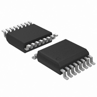
ADT7473ARQZ-1R7 ON Semiconductor, ADT7473ARQZ-1R7 Datasheet - Page 48

ADT7473ARQZ-1R7
Manufacturer Part Number
ADT7473ARQZ-1R7
Description
IC THERM MON FAN CTLR 16-QSOP
Manufacturer
ON Semiconductor
Series
dBCool®r
Datasheet
1.ADT7473ARQZ-1RL.pdf
(74 pages)
Specifications of ADT7473ARQZ-1R7
Function
Fan Control, Temp Monitor
Topology
ADC, Comparator, Fan Speed Counter, Multiplexer, Register Bank
Sensor Type
External & Internal
Sensing Temperature
-40°C ~ 125°C, External Sensor
Output Type
SMBus™
Output Alarm
No
Output Fan
Yes
Voltage - Supply
3 V ~ 3.6 V
Operating Temperature
-40°C ~ 125°C
Mounting Type
Surface Mount
Package / Case
16-QSOP
Full Temp Accuracy
+/- 0.5 C
Digital Output - Bus Interface
Serial (3-Wire, 4-Wire)
Maximum Operating Temperature
+ 125 C
Minimum Operating Temperature
- 40 C
Lead Free Status / RoHS Status
Lead free / RoHS Compliant
Available stocks
Company
Part Number
Manufacturer
Quantity
Price
Company:
Part Number:
ADT7473ARQZ-1R7
Manufacturer:
ON Semiconductor
Quantity:
500
Part Number:
ADT7473ARQZ-1R7
Manufacturer:
ADI/亚德诺
Quantity:
20 000
Step 11: Monitoring THERM
T
position while ensuring that the temperature never exceeds
the maximum operating temperature. Using the operating
point limit allows T
issues because of its self−corrective nature. In PC design, the
operating point for the chassis is usually the worst−case
internal chassis temperature.
determined by monitoring the thermal monitor in the Intel
Pentium 4 processor. To do this, the PROCHOT output of
the Pentium 4 is connected to the THERM input of the
ADT7473/ADT7473−1.
by allowing the current temperature to be copied to the
operating point register when the PROCHOT output pulls
the THERM input low on the ADT7473/ADT7473−1. This
gives the maximum temperature at which the Pentium 4 can
run before clock modulation occurs.
Enabling the THERM Trip Point as the Operating Point
Bits [4:2] of Dynamic T
enable/disable THERM monitoring to program the
operating point.
Dynamic T
Bit [4] PHTR2 = 1, copies the Remote 2 current temperature
to the Remote 2 operating point register, if THERM is
asserted. The operating point contains the temperature at
which THERM is asserted. This allows the system to run as
quietly as possible without affecting system performance.
PHTR2 = 0, ignores any THERM assertions. The Remote 2
operating point register reflects its programmed value.
Bit [3] PHTL = 1, copies the local current temperature to the
local temperature operating point register if THERM is
asserted. The operating point contains the temperature at
which THERM is asserted. This allows the system to run as
quietly as possible without affecting system performance.
PHTL = 0, ignores any THERM assertions. The local
temperature operating point register reflects its programmed
value.
MIN
OPERATING
Using the operating point limit ensures that the dynamic
The optimal operating point for the processor is
The operating point for the processor can be determined
HIGH TEMP
LOW TEMP
Figure 73. T
THERM
POINT
control mode operates in the best possible acoustic
LIMIT
LIMIT
LIMIT
T
MIN
MIN
HYSTERESIS
Control Register 1 (0x36)
ACTUAL
MIN
TEMP
Temperature Limit
Adjustments Limited by the High
MIN
to be independent of system−level
MIN
Control Register 1 (0x36)
T
FROM INCREASING
MIN
PREVENTED
http://onsemi.com
48
Bit [2] PHTR1 = 1, copies the Remote 1 current temperature
to the Remote 1 operating point register if THERM is
asserted. The operating point contains the temperature at
which THERM is asserted. This allows the system to run as
quietly as possible without affecting system performance.
PHTR1 = 0, ignores any THERM assertions. The Remote 1
operating point register reflects its programmed value.
Enabling Dynamic T
Bits [7:5] of the Dynamic T
enable/disable dynamic T
channels.
Dynamic
Bit [7] R2T = 1, enables dynamic T
Remote 2 temperature channel. The chosen T
dynamically adjusted based on the current temperature,
operating point, and high and low limits for this zone.
R2T = 0, disables dynamic T
chosen is not adjusted and the channel behaves as described
in the Automatic Fan Control Overview section.
Bit [6] LT = 1, enables dynamic T
temperature channel. The chosen T
adjusted based on the current temperature, operating point,
and high and low limits for this zone.
LT = 0, disables dynamic T
chosen is not adjusted and the channel behaves as described
in the Automatic Fan Control Overview section.
Bit [5] R1T = 1, enables dynamic T
Remote 1 temperature channel. The chosen T
dynamically adjusted based on the current temperature,
operating point, and high and low limits for this zone.
R1T = 0, disables dynamic T
chosen is not adjusted, and the channel behaves as described
in the Automatic Fan Control Overview section.
Enhancing System Acoustics
to changes in temperature; that is, the PWM duty cycle
responds immediately to temperature change. Any impulses
in temperature can cause an impulse in fan noise. For
psycho−acoustic reasons, the ADT7473/ADT7473−1 can
prevent the PWM output from reacting instantaneously to
temperature changes. Enhanced acoustic mode controls the
maximum change in PWM duty cycle at a given time. The
objective is to prevent the fan from cycling up and down,
annoying the user.
Acoustic Enhancement Mode Overview
control circuitry on the ADT7473/ADT7473−1 and shows
where acoustic enhancement fits in. Acoustic enhancement
is intended as a post design tweak made by a system or
mechanical engineer evaluating best settings for the system.
Having determined the optimal settings for the thermal
Automatic fan speed control mode reacts instantaneously
Figure 74 gives a top−level overview of the automatic fan
TMIN
Control Register 1 (0x36)
MIN
Control Mode
MIN
MIN
MIN
MIN
MIN
control on the temperature
Control Register 1 (0x36)
control. The T
control. The T
MIN
control. The T
MIN
value is dynamically
MIN
MIN
control on the local
control on the
control on the
MIN
MIN
MIN
MIN
MIN
value is
value is
value
value
value


