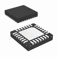
ISL62392HRTZ Intersil, ISL62392HRTZ Datasheet

ISL62392HRTZ
Specifications of ISL62392HRTZ
Available stocks
Related parts for ISL62392HRTZ
ISL62392HRTZ Summary of contents
Page 1
... Ordering Information PART NUMBER PART TEMP (Note) MARKING RANGE (°C) ISL62391HRTZ* 623 91HRTZ -10 to +100 ISL62392HRTZ* 623 92HRTZ -10 to +100 ISL62391CHRTZ* 62391C HRTZ -10 to +100 ISL62392CHRTZ* 62392C HRTZ -10 to +100 ISL62391IRTZ* 623 91IRTZ -40 to +100 ...
Page 2
... Recommended Operating Conditions Ambient Temperature Range ISL62391IRTZ .-40°C to +100°C ISL62392IRTZ .-40°C to +100°C Ambient Temperature Range ISL62391HRTZ .-10°C to +100°C ISL62392HRTZ .-10°C to +100°C Supply Voltage (VIN to GND 5.5V to 25V = -40°C to +100°C, unless otherwise noted. Typical values are CONDITIONS Rising Threshold ...
Page 3
... Rising Edge (ISL62391HRTZ, ISL62392HRTZ -10°C to +100°C) A Falling Edge Falling Edge (ISL62391HRTZ, ISL62392HRTZ -10°C to +100°C) A VOUT regulated 0.6V (ISL62391HRTZ, ISL62392HRTZ -10°C to +100° 300kHz (Note 3) SW VIN ≥ 6V for VOUT = 5.5V PGOOD = VCC EN1 = EN2 = 1 EN1 = 1, EN2 = Floating or EN1 = Floating, EN2 =1 ...
Page 4
... Typical values are CONDITIONS EN = GND or VCC EN = VCC EN = GND EN = VCC EN = GND EN = VCC EN = VCC (ISL62391HRTZ, ISL62392HRTZ -10°C to +100°C) A Falling edge, referenced to FB Falling edge, referenced to FB (ISL62391HRTZ, ISL62392HRTZ -10°C to +100°C) A Rising edge, referenced to FB ...
Page 5
ISL62391, ISL62392, ISL62391C, ISL62392C Functional Pin Description PIN NAME 1 PGOOD Open-drain power-good status outputs. Connect to VCC through a 100k resistor. Output will be high when all outputs are within regulation with no faults detected. 2 FSET2 Frequency control ...
Page 6
ISL62391, ISL62392, ISL62391C, ISL62392C Typical Application Circuits The typical application circuits generate the 5V/8A and 3.3V/8A (system regulator), or 1.05V/15A and 1.5V/15A (chip set) supplies in a notebook computer. The input supply (VBAT) range is 5.5V to 25V ...
Page 7
ISL62391, ISL62392, ISL62391C, ISL62392C Typical Application Circuits 4x10µF 0.22µF IRF7821 2.2µ 2x330µF 14k 0.022µF IRF7832 14k 590 36.5k 1800pF 48.7k 4.7µF 1µF 1µF FIGURE 3. TYPICAL CHIP SET APPLICATION CIRCUIT WITH INDUCTOR ...
Page 8
ISL62391, ISL62392, ISL62391C, ISL62392C Block Diagram FSET1/2 FB1/2 V 0.6V REF FCCM VOUT1/2 SOFT DISCHARGE EN1 START-UP AND EN2 SHUTDOWN LOGIC LDO3EN 10µA OCSET1/2 ISEN1 16% REF FB1 16% REF *In addition to being used for ...
Page 9
ISL62391, ISL62392, ISL62391C, ISL62392C Typical Performance Curves 100 19V 0.10 1.00 I (A) OUT FIGURE 5. CHANNEL 1 EFFICIENCY AT V OPERATION. HIGH-SIDE ...
Page 10
ISL62391, ISL62392, ISL62391C, ISL62392C Typical Performance Curves V O1 PHASE1 V O2 PHASE2 FIGURE 11. CCM STEADY-STATE OPERATION 3.3V 5A PHASE1 V O2 PHASE2 FIGURE 13. AUDIO FILTER OPERATION, ...
Page 11
ISL62391, ISL62392, ISL62391C, ISL62392C Typical Performance Curves EN1 FIGURE 17. DELAYED START 12V EN2 = FLOAT, NO LOAD PGOOD FIGURE 19. DELAYED START 12V ...
Page 12
... Modulator and Switching Frequency The ISL62391, ISL62392, ISL62391C and ISL62392C 3 modulator feature Intersil’s R technology, a hybrid of fixed frequency PWM and variable frequency hysteretic control. 3 Intersil’s R technology can simultaneously affect the PWM switching frequency and PWM duty cycle in response to input voltage and output load transients ...
Page 13
ISL62391, ISL62392, ISL62391C, ISL62392C 1.5ms t SOFTSTART 2.75ms PGOOD DELAY FIGURE 24. SOFT-START SEQUENCE FOR ONE SMPS The PGOOD pin indicates when the converter is capable of supplying regulated voltage undefined impedance not above ...
Page 14
ISL62391, ISL62392, ISL62391C, ISL62392C over the entire load range. This will produce the best transient response to all load conditions, but will have increased light-load power loss. If FCCM is forced low, the ISL62391, ISL62392, ISL62391C and ISL62392C will automatically ...
Page 15
ISL62391, ISL62392, ISL62391C, ISL62392C Where (Ω) is the resistor used to program the OCSET overcurrent setpoint - I is the output current threshold that will activate the OC OCP circuit - DCR is the inductor DC resistance For ...
Page 16
... It is assumed that the reader is familiar with many of the basic skills and techniques referenced in the following section. In addition to this guide, Intersil provides form the Type-II complete reference designs that include schematics, bills of materials, and example board layouts. ...
Page 17
ISL62391, ISL62392, ISL62391C, ISL62392C The inductance of the capacitor can cause a brief voltage dip if the load transient has an extremely high slew rate. Low inductance capacitors should be considered in this scenario. A capacitor dissipates heat as a ...
Page 18
ISL62391, ISL62392, ISL62391C, ISL62392C Where the difference of the DC component of the VALLEY inductor current minus 1/2 of the inductor ripple current - I is the sum of the DC component of the inductor PEAK current ...
Page 19
... Accordingly, the reader is cautioned to verify that data sheets are current before placing orders. Information furnished by Intersil is believed to be accurate and reliable. However, no responsibility is assumed by Intersil or its subsidiaries for its use; nor for any infringements of patents or other rights of third parties which may result from its use ...
Page 20
ISL62391, ISL62392, ISL62391C, ISL62392C Package Outline Drawing L28.4x4 28 LEAD THIN QUAD FLAT NO-LEAD PLASTIC PACKAGE Rev 0, 9/ PIN 1 INDEX AREA TOP VIEW (3 . 20) PACKAGE BOUNDARY ( 50) TYPICAL ...


