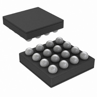
LM3554TME/NOPB National Semiconductor, LM3554TME/NOPB Datasheet - Page 36

LM3554TME/NOPB
Manufacturer Part Number
LM3554TME/NOPB
Description
IC LED DVR PHOTO FLASH 16-USMD
Manufacturer
National Semiconductor
Type
Photo Flash LED (I²C Interface)r
Datasheet
1.LM3554TMENOPB.pdf
(40 pages)
Specifications of LM3554TME/NOPB
Constant Current
Yes
Topology
High Side, Step-Up (Boost)
Number Of Outputs
2
Internal Driver
Yes
Type - Primary
Flash/Torch
Type - Secondary
White LED
Frequency
2MHz
Voltage - Supply
2.7 V ~ 5.5 V
Voltage - Output
5V
Mounting Type
Surface Mount
Package / Case
16-MicroSMD
Operating Temperature
-30°C ~ 85°C
Current - Output / Channel
600mA
Internal Switch(s)
Yes
Efficiency
90%
Led Driver Application
LED Backlighting, Portable Electronics
No. Of Outputs
2
Output Current
1.2A
Input Voltage
2.7V To 5.5V
Dimming Control Type
I2C
Rohs Compliant
Yes
Lead Free Status / RoHS Status
Lead free / RoHS Compliant
Other names
LM3554TMETR
www.national.com
NTC THERMISTOR SELECTION
NTC thermistors have a temperature to resistance relation-
ship of:
where β is given in the thermistor datasheet and R
thermistors value at +25°C. R3 in
it is equal to:
where R(T)
point, V
Another useful equation for the thermistor resistive divider is
developed by combining the equations for R3, and R(T) and
solving for temperature. This gives the following relationship.
Using a spreadsheet such as Excel, different curves for the
temperature trip point T(°C) can be created vs R3, Beta, or
BIAS
TRIP
is shown in
is the thermistors value at the temperature trip
Figure
FIGURE 24. Thermistor Resistive Divider Response vs Temperature
25, and V
Figure 25
TRIP
is chosen so that
= 1.05V (typical).
25C
is the
36
Choosing R3 here gives a more linear response around the
temperature trip voltage. For example, with V
thermistor whose nominal value at +25°C is 100kΩ and a β =
4500K, the trip point is chosen to be +93°C. The value of R
(T) at 93°C is:
Figure 24
of the previous example.
V
for practical values of thermistors, series resistors (R3), or
reference voltages V
Programming bit [3] of the Configuration register with a (1)
selects Thermal Comparator mode making the LEDI/NTC pin
a comparator input for flash LED thermal sensing.
shows the internal block diagram of the thermal sensing cir-
cuit which is OR’d with both the TX1 and ENVM/TX2 (TX2
mode) to force the LM3554 from Flash to Torch mode. This
is intended to prevent LED overheating during flash pulses.
BIAS
in order to help better choose the thermal components
shows the linearity of the thermistor resistive divider
30042034
BIAS
.
BIAS
= 2.5V, a
Figure 25


