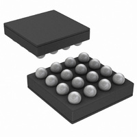
LM3554TME/NOPB National Semiconductor, LM3554TME/NOPB Datasheet - Page 29

LM3554TME/NOPB
Manufacturer Part Number
LM3554TME/NOPB
Description
IC LED DVR PHOTO FLASH 16-USMD
Manufacturer
National Semiconductor
Type
Photo Flash LED (I²C Interface)r
Datasheet
1.LM3554TMENOPB.pdf
(40 pages)
Specifications of LM3554TME/NOPB
Constant Current
Yes
Topology
High Side, Step-Up (Boost)
Number Of Outputs
2
Internal Driver
Yes
Type - Primary
Flash/Torch
Type - Secondary
White LED
Frequency
2MHz
Voltage - Supply
2.7 V ~ 5.5 V
Voltage - Output
5V
Mounting Type
Surface Mount
Package / Case
16-MicroSMD
Operating Temperature
-30°C ~ 85°C
Current - Output / Channel
600mA
Internal Switch(s)
Yes
Efficiency
90%
Led Driver Application
LED Backlighting, Portable Electronics
No. Of Outputs
2
Output Current
1.2A
Input Voltage
2.7V To 5.5V
Dimming Control Type
I2C
Rohs Compliant
Yes
Lead Free Status / RoHS Status
Lead free / RoHS Compliant
Other names
LM3554TMETR
FLASH BRIGHTNESS REGISTER
Bits [2:0] of the Torch Brightness Register, or bits [2:0] of the
Flash Brightness Register place the device in shutdown or
control the on/off state of Torch, Flash, the Indicator LED and
the Voltage output mode. Writing to the Flash Brightness
STROBE Edge or Level
Select
0 = (Level Sensitive) When
STROBE goes high, Flash
current will turn on and
remain on for the duration
the STROBE pin is held
high
Timeout occurs, whichever
comes first.(default)
1 = (Edge Triggered) When
STROBE goes high , Flash
current will turn on and
remain on for the duration
of the Flash Timeout.
or
Bit 7 (STR)
when
Flash
Flash Current Select Bits
0000 = 35.5mA (71mA total)
0001 = 73mA (146mA total)
0010 = 109mA (218mA total)
0011 = 147.5mA (295mA total)
0100 = 182.5mA (365mA total)
0101 = 220.5mA (441mA total)
0110 = 259mA (518mA total)
111 = 298mA (596mA total)
1000 =326mA (652mA total)
1001 = 364.5mA (729mA total)
1010 = 402.5mA (805mA total)
1011 = 440.5mA (881mA total)
1100 = 480mA (960mA total)
1101 = 518.5mA (1037mA total) Default
1110 = 556.5mA (1113mA total)
1111 = 595.5mA (1191mA total)
Bit 6 (FC3)
FIGURE 17. Flash Brightness Register Description
TABLE 3. Flash Brightness Register Bit Settings
Bit 5 (FC2)
Bit 4 (FC1) Bit 3 (FC0)
29
Register bits [2:0] automatically updates the Torch Brightness
Register bits [2:0]. Bits [6:3] set the current level in Flash
mode (see
select bit (STR) (see
Table
Enable Bits
000 = Shutdown (default)
001 = Indicator Mode
010 = Torch Mode
011 = Flash Mode (bits reset at timeout)
100 = Voltage Output Mode
101 = Voltage Output + Indicator Mode
110 = Voltage Output + Torch Mode
111 = Voltage Output + Flash Mode (bits
[1:0] are reset at end of timeout)
Bit 2 (VM)
3). Bit [7] sets the STROBE Termination
Table
3).
Bit 1 (EN1)
30042022
Bit 0 (EN0)
www.national.com


