LM3554TME/NOPB National Semiconductor, LM3554TME/NOPB Datasheet - Page 25
LM3554TME/NOPB
Manufacturer Part Number
LM3554TME/NOPB
Description
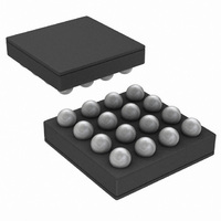
IC LED DVR PHOTO FLASH 16-USMD
Manufacturer
National Semiconductor
Type
Photo Flash LED (I²C Interface)r
Datasheet
1.LM3554TMENOPB.pdf
(40 pages)
Specifications of LM3554TME/NOPB
Constant Current
Yes
Topology
High Side, Step-Up (Boost)
Number Of Outputs
2
Internal Driver
Yes
Type - Primary
Flash/Torch
Type - Secondary
White LED
Frequency
2MHz
Voltage - Supply
2.7 V ~ 5.5 V
Voltage - Output
5V
Mounting Type
Surface Mount
Package / Case
16-MicroSMD
Operating Temperature
-30°C ~ 85°C
Current - Output / Channel
600mA
Internal Switch(s)
Yes
Efficiency
90%
Led Driver Application
LED Backlighting, Portable Electronics
No. Of Outputs
2
Output Current
1.2A
Input Voltage
2.7V To 5.5V
Dimming Control Type
I2C
Rohs Compliant
Yes
Lead Free Status / RoHS Status
Lead free / RoHS Compliant
Other names
LM3554TMETR


FLAGS REGISTER AND FAULT INDICATORS
The Flags Register (0xD0) contains the Interrupt and Fault
indicators. Five fault flags are available in the LM3554. These
include a Thermal Shutdown, an LED Failure Flag (LEDF) , a
Timeout indicator Flag (TO), a LED Thermal Flag (NTC), and
a VIN Monitor Flag. Additionally, two interrupt flag bits TX in-
terrupt and TX2 interrupt indicate a change of state of the TX1/
TORCH pin (TX1 mode) and ENVM/TX2 pin (TX2 mode).
Reading back a "1" indicates the TX lines have changed state
since the last read of the Flags Register. A read of the Flags
Register resets these bits.
Thermal Shutdown
When the LM3554’s die temperature reaches +150°C the
boost converter shuts down, and the NFET and PFET turn off.
Additionally, all three current sources (LED1, LED2, and LE-
DI) turn off. When the thermal shutdown threshold is tripped
a (1) gets written to bit [1] of the Flag Register (Thermal Shut-
down bit). The LM3554 will start up again when the die
temperature falls to below +135°C.
During heavy load conditions when the internal power dissi-
pation in the device causes thermal shutdown, the part will
turn off and start up again after the die temperature cools. This
will result in a pulsed on/off operation. The OVT bit however
will only get written once. To reset the OVT bit pull HWEN low,
power down the LM3554, or read the Flags Register.
LED Fault
The LED Fault flag (bit 2 of the Flags Register) reads back a
(1) if the part is active in Flash or Torch mode and either LED1
or LED2 experience an open or short condition. An LED open
condition is signaled if the OVP threshold is crossed at OUT
while the device is in Flash or Torch mode. An LED short
condition is signaled if the voltage at LED1 or LED2 goes be-
low 500mV while the device is in Torch or Flash mode.
There is a delay of 250µs before the LEDF flag is valid on a
LED short. This is the time from when VLED falls below the
LED short threshold of 500mV (typical) to when the fault flag
is valid. There is a delay of 2µs from when the LEDF flag is
valid on an LED open. This delay is the time between when
the OVP threshold is triggered and when the fault flag is valid.
The LEDF flag can only be reset to (0) by pulling HWEN low,
removing power to the LM3554, or reading the Flags Register.
25
Flash Timeout
The TO flag (bit [0] of the Flags Register) reads back a (1) if
the LM3554 is active in Flash mode and the Timeout period
expires before the Flash pulse is terminated. The flash pulse
can be terminated before the Timeout period expires by
pulling the STROBE pin low (with STR bit '0'), or by writing a
‘0’ to bit 0 or 1 of the Torch Brightness Register or the Flash
Brightness Register. The TO flag is reset to (0) by pulling
HWEN low, removing power to the LM3554, reading the Flags
Register, or when the next Flash pulse is triggered.
LED Thermal Fault
The NTC flag (bit [5] of the Flags Register) reads back a (1)
if the LM3554 is active in Flash or Torch mode, the device is
in NTC mode, and the voltage at LEDI/NTC has fallen below
V
LM3554 has been forced into Torch or LED shutdown (de-
pending on the state of Configuration Register 2 bit [1], the
Flags Register must be read in order to place the device back
in normal operation. (See
section for more details.)
Input Voltage Monitor Fault
The V
a '1' when the Input Voltage Monitor is enabled and V
below the programmed VIN Monitor threshold. This flag must
be read back in order to resume normal operation after the
LED current has been forced to Torch mode or turned off due
to a VIN Monitor event.
TX1 and TX2 Interrupt Flags
The TX1 and TX2 interrupt flags (bits [3] and [4]) indicate a
TX event on the TX1/TORCH and ENVM/TX2 pins. Bit 3 will
read back a (1) if TX1/TORCH is in TX1 mode and the pin has
changed from low to high since the last read of the Flags
Register. Bit 4 will read back a (1) if ENVM/TX2 is in TX2
mode and the pin has had a TX event since the last read of
the Flags Register. A read of the Flags Register automatically
resets these bits.
The ENVM/TX2/GPIO2 pin, when configured in TX2 mode,
has a TX event that can be either a high-to-low transition or
a low-to-high transition depending on the setting of the TX2
polarity bit (see Configuration Register 1 Bit [6]).
TRIP
IN
(1.05V typical). When this has happened and the
Monitor Flag (bit [6] of the Flag Register) reads back
Thermal Comparator Mode (NTC)
www.national.com
IN
falls
Related parts for LM3554TME/NOPB
Image
Part Number
Description
Manufacturer
Datasheet
Request
R

Part Number:
Description:
LM3554 PRODUCT BRIEF Synchronous Boost Converter with 1.2A Dual High Side LED Drivers and I<sup>2</sup>C Compatible Interface; Package: MICRO SMD; No of Pins: 16; Qty per Container: 250/Reel
Manufacturer:
National Semiconductor
Part Number:
Description:
National Semiconductor [8-Bit D/A Converter]
Manufacturer:
National Semiconductor
Datasheet:
Part Number:
Description:
National Semiconductor [Media Coprocessor]
Manufacturer:
National Semiconductor
Datasheet:
Part Number:
Description:
Digitally Controlled Tone and Volume Circuit with Stereo Audio Power Amplifier, Microphone Preamp Stage and National 3D Sound
Manufacturer:
National Semiconductor
Datasheet:
Part Number:
Description:
Digitally Controlled Tone and Volume Circuit with Stereo Audio Power Amplifier, Microphone Preamp Stage and National 3D Sound
Manufacturer:
National Semiconductor
Datasheet:
Part Number:
Description:
AC97 Rev 2 Codec with Sample Rate Conversion and National 3D Sound
Manufacturer:
National Semiconductor
Part Number:
Description:
Manufacturer:
National Semiconductor
Datasheet:
Part Number:
Description:
Manufacturer:
National Semiconductor
Datasheet:
Part Number:
Description:
General Purpose, Low Voltage, Low Power, Rail-to-Rail Output Operational Amplifiers
Manufacturer:
National Semiconductor
Datasheet:
Part Number:
Description:
8-bit 20 MSPS flash A/D converter.
Manufacturer:
National Semiconductor
Datasheet:
Part Number:
Description:
Low Noise Quad Operational Amplifier
Manufacturer:
National Semiconductor
Datasheet:
Part Number:
Description:
Quad Differential Line Receivers
Manufacturer:
National Semiconductor
Datasheet:
Part Number:
Description:
Quad High Speed Trapezoidal? Bus Transceiver
Manufacturer:
National Semiconductor
Datasheet:
Part Number:
Description:
Dual Line Receiver
Manufacturer:
National Semiconductor
Datasheet: