LM3554TME/NOPB National Semiconductor, LM3554TME/NOPB Datasheet - Page 34
LM3554TME/NOPB
Manufacturer Part Number
LM3554TME/NOPB
Description
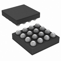
IC LED DVR PHOTO FLASH 16-USMD
Manufacturer
National Semiconductor
Type
Photo Flash LED (I²C Interface)r
Datasheet
1.LM3554TMENOPB.pdf
(40 pages)
Specifications of LM3554TME/NOPB
Constant Current
Yes
Topology
High Side, Step-Up (Boost)
Number Of Outputs
2
Internal Driver
Yes
Type - Primary
Flash/Torch
Type - Secondary
White LED
Frequency
2MHz
Voltage - Supply
2.7 V ~ 5.5 V
Voltage - Output
5V
Mounting Type
Surface Mount
Package / Case
16-MicroSMD
Operating Temperature
-30°C ~ 85°C
Current - Output / Channel
600mA
Internal Switch(s)
Yes
Efficiency
90%
Led Driver Application
LED Backlighting, Portable Electronics
No. Of Outputs
2
Output Current
1.2A
Input Voltage
2.7V To 5.5V
Dimming Control Type
I2C
Rohs Compliant
Yes
Lead Free Status / RoHS Status
Lead free / RoHS Compliant
Other names
LM3554TMETR


www.national.com
V
The V
Monitor comparator as well as selects the 4 programmable
Reads Back '1'
Reads Back '1' Reads Back '1' Reads Back '1' Reads Back '1' Reads Back '0'
IN
Bit 7 (Not
Bit 7 (Not
MONITOR REGISTER
Used)
used)
IN
Monitor Register controls the on/off state of the V
External Flag)
pin will pull low
a GPIO output
when the LED
Thermal Fault
External Flag
configured as
ENVM/TX2/
TX2/GPIO2
Bit 6 (NTC
the ENVM/
Flag is set
Bit 6 (Not
1 = When
(default)
GPIO2 is
0 = NTC
disabled
mode is
used)
Bit 5 (ENVM/
This bit is the
(default is 0)
GPIO2 pin in
read or write
TX2/GPIO2
ENVM/TX2/
GPIO mode
data for the
Bit 5 (Not
used)
data)
FIGURE 23. V
TABLE 9. V
TABLE 8. GPIO Register Bit Settings
a GPIO Output
TX2/GPIO2 is
TX2/GPIO2 is
Bit 4 (ENVM/
a GPIO Input
TX2/GPIO2
0 = ENVM/
1 = ENVM/
Bit 4 (Not
direction)
(default)
used)
IN
data
IN
Monitor Register Bit Settings
Monitor Register Description
IN
34
TX2/GPIO2 is
TX2/GPIO2 is
Bit 3 (ENVM/
Configuration
configured as
Register bit 5
according to
TX2/GPIO2
0 = ENVM/
1 = ENVM/
configured
Bit 3 (Not
Control)
(default)
thresholds.
the V
a GPIO
used)
the
IN
Monitor feature.
Figure 23
01=3.2V threshold (V
This bit is the
TX1/TORCH/
(default is 0)
GPIO1 data)
GPIO1 pin in
read or write
GPIO mode
data for the
Threshold)
Bit 2 (TX1/
Bit 2 (VIN
TORCH/
00 = 3.1V threshold (V
10 = 3.3V threshold (V
11 = 3.4V threshold (V
falling) Default
and
falling)
falling)
Table 9
GPIO1 is an
GPIO1 data
Threshold)
Bit 1 (TX1/
GPIO1 is a
GPIO input
direction)
Bit 1 (VIN
(default)
TORCH/
0 = TX1/
TORCH/
TORCH/
1 = TX!/
output
describe the bit settings of
IN
falling)
IN
IN
IN
30042047
Comparator is
Comparator is
configured as
configured as
an active low
GPIO1 pin is
GPIO1 pin is
Bit 0 (TX1/
Monitoring
Monitoring
reset input
Bit 0 (VIN
Control)
(default)
(default)
enabled.
TORCH/
0 = TX1/
TORCH/
1 = TX1/
TORCH/
disabled
Monitor
Enable)
a GPIO
0 = V
1 = V
GPIO1
IN
IN
Related parts for LM3554TME/NOPB
Image
Part Number
Description
Manufacturer
Datasheet
Request
R

Part Number:
Description:
LM3554 PRODUCT BRIEF Synchronous Boost Converter with 1.2A Dual High Side LED Drivers and I<sup>2</sup>C Compatible Interface; Package: MICRO SMD; No of Pins: 16; Qty per Container: 250/Reel
Manufacturer:
National Semiconductor
Part Number:
Description:
National Semiconductor [8-Bit D/A Converter]
Manufacturer:
National Semiconductor
Datasheet:
Part Number:
Description:
National Semiconductor [Media Coprocessor]
Manufacturer:
National Semiconductor
Datasheet:
Part Number:
Description:
Digitally Controlled Tone and Volume Circuit with Stereo Audio Power Amplifier, Microphone Preamp Stage and National 3D Sound
Manufacturer:
National Semiconductor
Datasheet:
Part Number:
Description:
Digitally Controlled Tone and Volume Circuit with Stereo Audio Power Amplifier, Microphone Preamp Stage and National 3D Sound
Manufacturer:
National Semiconductor
Datasheet:
Part Number:
Description:
AC97 Rev 2 Codec with Sample Rate Conversion and National 3D Sound
Manufacturer:
National Semiconductor
Part Number:
Description:
Manufacturer:
National Semiconductor
Datasheet:
Part Number:
Description:
Manufacturer:
National Semiconductor
Datasheet:
Part Number:
Description:
General Purpose, Low Voltage, Low Power, Rail-to-Rail Output Operational Amplifiers
Manufacturer:
National Semiconductor
Datasheet:
Part Number:
Description:
8-bit 20 MSPS flash A/D converter.
Manufacturer:
National Semiconductor
Datasheet:
Part Number:
Description:
Low Noise Quad Operational Amplifier
Manufacturer:
National Semiconductor
Datasheet:
Part Number:
Description:
Quad Differential Line Receivers
Manufacturer:
National Semiconductor
Datasheet:
Part Number:
Description:
Quad High Speed Trapezoidal? Bus Transceiver
Manufacturer:
National Semiconductor
Datasheet:
Part Number:
Description:
Dual Line Receiver
Manufacturer:
National Semiconductor
Datasheet: