DS1862AB+ Maxim Integrated Products, DS1862AB+ Datasheet - Page 7
DS1862AB+
Manufacturer Part Number
DS1862AB+
Description
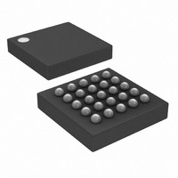
IC LASR CTRLR 7CHAN 5.5V 25CSBGA
Manufacturer
Maxim Integrated Products
Type
Laser Diode Controller (Fiber Optic)r
Datasheet
1.DS1862ABTR.pdf
(42 pages)
Specifications of DS1862AB+
Data Rate
10Gbps
Number Of Channels
7
Voltage - Supply
2.9 V ~ 5.5 V
Current - Supply
3mA
Operating Temperature
-40°C ~ 100°C
Package / Case
25-CSBGA
Mounting Type
Surface Mount
Lead Free Status / RoHS Status
Lead free / RoHS Compliant


Note 1: All voltages are referenced to ground. Current into the IC is positive, and current out of the IC is negative.
Note 2: Secondary power supply is used to support optional variable power-supply feature of the XFP module. If V
Note 3: Input signals (i.e., TX-D, MOD-DESEL, and P-DOWN/RST) have internal pullup resistors.
Note 4: Guaranteed by design. Simulated over process and 50μA < I
Note 5: C
Note 6: EEPROM write begins after a STOP condition occurs.
Note 7: This is the maximum and minimum voltage on the MODSET and BIASSET pins required to meet accuracy and drift specifi-
Note 8: For V
Note 9: This is the uncalibrated offset provided by the factory; offset adjustment is available on this channel.
Note 10: %FS refers to calibrated FS in case of internal calibration, and uncalibrated FS in the case of external calibration.
Note 11: See the Monitor Channels section for more detail or V
FAST ALARMS AND V
(V
NONVOLATILE MEMORY CHARACTERISTICS
(V
HIGH BIAS and TX-P Threshold
FS
V
Falling Edge Delay
QT Temperature Coefficient
QT Voltage Coefficient
QT FS Trim Accuracy (4.2V,
+25°C)
QT Accuracy (Trip) (INL)
QT Voltco
QT Tempco
Endurance (Write Cycle)
Endurance (Write Cycle)
CC2/3
CC3
CC3
= +2.9V to +5.5V, V
= +2.9V to +5.5V, unless otherwise noted.)
Fault Asserted
(i.e., signal conditioners using 3.3V supply), V
cations.
Uncalibrated FS is set in the factory and specified in this data sheet as FS (factory). Calibrated FS is set by the user, allow-
ing a change in any monitored channel scale.
PARAMETER
PARAMETER
B
XFP Laser Control and Digital Diagnostic IC
—total capacitance of one bus line in picofarads.
THRSET
_______________________________________________________________________________________
, offset may be as much as 10mV.
CC2
= +1.6V to +3.6V, T
CC
SYMBOL
SYMBOL
FAULT CHARACTERISTICS
(Note 11)
+70°C
+25°C
(Note 10)
A
V
= -40°C to +100°C, unless otherwise noted.)
CC2/3
CC2
should be connected to the V
CC2
CONDITIONS
CONDITIONS
and V
BMD
CC3
< 1500μA.
selection.
CC3
.
2.480
200k
2.48
MIN
MIN
50k
-3
-2
2.500
TYP
TYP
2.5
1.5
0
2.520
MAX
MAX
2.52
0.5
0.5
+3
+2
75
CC2
3
is not used
Cycles
Cycles
UNITS
UNITS
LSB
%/V
%/V
mA
mA
ms
%
%
7
Related parts for DS1862AB+
Image
Part Number
Description
Manufacturer
Datasheet
Request
R

Part Number:
Description:
XFP Laser Control and Digital Diagnostic IC
Manufacturer:
Maxim Integrated Products
Part Number:
Description:
MAX7528KCWPMaxim Integrated Products [CMOS Dual 8-Bit Buffered Multiplying DACs]
Manufacturer:
Maxim Integrated Products
Datasheet:
Part Number:
Description:
Single +5V, fully integrated, 1.25Gbps laser diode driver.
Manufacturer:
Maxim Integrated Products
Datasheet:
Part Number:
Description:
Single +5V, fully integrated, 155Mbps laser diode driver.
Manufacturer:
Maxim Integrated Products
Datasheet:
Part Number:
Description:
VRD11/VRD10, K8 Rev F 2/3/4-Phase PWM Controllers with Integrated Dual MOSFET Drivers
Manufacturer:
Maxim Integrated Products
Datasheet:
Part Number:
Description:
Highly Integrated Level 2 SMBus Battery Chargers
Manufacturer:
Maxim Integrated Products
Datasheet:
Part Number:
Description:
Current Monitor and Accumulator with Integrated Sense Resistor; ; Temperature Range: -40°C to +85°C
Manufacturer:
Maxim Integrated Products
Part Number:
Description:
TSSOP 14/A�/RS-485 Transceivers with Integrated 100O/120O Termination Resis
Manufacturer:
Maxim Integrated Products
Part Number:
Description:
TSSOP 14/A�/RS-485 Transceivers with Integrated 100O/120O Termination Resis
Manufacturer:
Maxim Integrated Products
Part Number:
Description:
QFN 16/A�/AC-DC and DC-DC Peak-Current-Mode Converters with Integrated Step
Manufacturer:
Maxim Integrated Products
Part Number:
Description:
TDFN/A/65V, 1A, 600KHZ, SYNCHRONOUS STEP-DOWN REGULATOR WITH INTEGRATED SWI
Manufacturer:
Maxim Integrated Products
Part Number:
Description:
Integrated Temperature Controller f
Manufacturer:
Maxim Integrated Products
Part Number:
Description:
SOT23-6/I�/45MHz to 650MHz, Integrated IF VCOs with Differential Output
Manufacturer:
Maxim Integrated Products
Part Number:
Description:
SOT23-6/I�/45MHz to 650MHz, Integrated IF VCOs with Differential Output
Manufacturer:
Maxim Integrated Products
Part Number:
Description:
EVALUATION KIT/2.4GHZ TO 2.5GHZ 802.11G/B RF TRANSCEIVER WITH INTEGRATED PA
Manufacturer:
Maxim Integrated Products