DS1862AB+ Maxim Integrated Products, DS1862AB+ Datasheet - Page 24
DS1862AB+
Manufacturer Part Number
DS1862AB+
Description
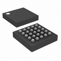
IC LASR CTRLR 7CHAN 5.5V 25CSBGA
Manufacturer
Maxim Integrated Products
Type
Laser Diode Controller (Fiber Optic)r
Datasheet
1.DS1862ABTR.pdf
(42 pages)
Specifications of DS1862AB+
Data Rate
10Gbps
Number Of Channels
7
Voltage - Supply
2.9 V ~ 5.5 V
Current - Supply
3mA
Operating Temperature
-40°C ~ 100°C
Package / Case
25-CSBGA
Mounting Type
Surface Mount
Lead Free Status / RoHS Status
Lead free / RoHS Compliant


XFP Laser Control and Digital Diagnostic IC
During an asserted period of P-DOWN/RST (DS1862A
in power-down), and V
remains in power-down mode upon power-up. While in
power-down mode the INTERRUPT pin does not assert.
Once V
after the interrupt assert delay, t
Besides powering down the DS1862A, the P-
DOWN/RST pin also functions to reset the DS1862A.
After a high-going pulse of time t
occur within the DS1862A. First, MODSET and BIASSET
currents shut down and are then reinstated. Second,
between the rising edge of the reset pulse and the
assertion of the reset-done flag (t
is ignored and does not cause FETG to trip. After time
t
time, the reset-done flag is asserted, causing an inter-
rupt to be generated. If there are no faults before t
then no interrupts are asserted on the INTERRUPT pin.
If V
the reset-done flag must be cleared twice. The first time
the reset-done flag is generated by V
the second time reset-done is generated by a falling
edge on P-DOWN/RST. If V
ered while P-DOWN/RST is low then only one reset-
done flag needs to be cleared. See the timing
diagrams for graphical detail.
The DS1862A features six separate memory tables that
are internally organized into 4-word rows. The Lower
Memory is addressed from 00h to 7Fh and contains
alarm and warning thresholds, flags, masks, several
control registers, password entry area (PE), and the
24
INIT,
CC3
______________________________________________________________________________________
the low TX-P flag becomes functional. Also, at this
CC3
is powered up while P-DOWN/RST is high, then
has returned, the reset done flag asserts
CC3
Memory Organization
CC3
is cycled, the DS1862A
INIT_ON
INIT
RESET
is continuously pow-
Reset Functionality
Memory Map
), the low TX-P flag
CC3
.
, several events
powering up,
INIT
,
table select byte. Table 01h primarily contains user
EEPROM as well as several control bytes for various
functions. Table 02h is strictly user EEPROM that is pro-
tected by a host password. Table 03h is strictly used
for controlling the extinction ratio with an LUT. Table
04h is a multifunction space that contains internal cali-
bration values for monitored channels, LUT index point-
ers, and miscellaneous control bytes. Table 05h is
factory programmed and stores SCALE values for use
with suggested external temperature sensors. Also, one
byte in Table 05h controls the THRSET voltage source
and is completely accessible without any password
protection. See the Detailed Register Description sec-
tion for a more complete detail of each byte’s function,
as well as Table 11 for read/write permissions for each
byte. Many nonvolatile memory locations are actually
SRAM-shadowed EEPROM, which are controlled by the
SEEB bit in Table 04h, Byte B2h.
The DS1862A incorporates SRAM-shadowed EEP-
ROM memory locations for key memory addresses
that may be rewritten many times. By default the shad-
owed-EEPROM bit, SEEB, is not set and these loca-
tions act as ordinary EEPROM. By setting SEEB, these
locations begin to function like SRAM cells, which allow
an infinite number of write cycles without concern of
wearing out the EEPROM. This also eliminates the
requirement for the EEPROM write time, t
changes made with SEEB enabled do not affect the
EEPROM, these changes are not retained through
power cycles. The power-up value is the last value writ-
ten with SEEB disabled. This function can be used to
limit the number of EEPROM writes during calibration or
to change the monitor thresholds periodically during
normal operation helping to reduce the number of times
EEPROM is written. The following information describes
which locations are shadowed-EEPROM.
WR
. Because
Related parts for DS1862AB+
Image
Part Number
Description
Manufacturer
Datasheet
Request
R

Part Number:
Description:
XFP Laser Control and Digital Diagnostic IC
Manufacturer:
Maxim Integrated Products
Part Number:
Description:
MAX7528KCWPMaxim Integrated Products [CMOS Dual 8-Bit Buffered Multiplying DACs]
Manufacturer:
Maxim Integrated Products
Datasheet:
Part Number:
Description:
Single +5V, fully integrated, 1.25Gbps laser diode driver.
Manufacturer:
Maxim Integrated Products
Datasheet:
Part Number:
Description:
Single +5V, fully integrated, 155Mbps laser diode driver.
Manufacturer:
Maxim Integrated Products
Datasheet:
Part Number:
Description:
VRD11/VRD10, K8 Rev F 2/3/4-Phase PWM Controllers with Integrated Dual MOSFET Drivers
Manufacturer:
Maxim Integrated Products
Datasheet:
Part Number:
Description:
Highly Integrated Level 2 SMBus Battery Chargers
Manufacturer:
Maxim Integrated Products
Datasheet:
Part Number:
Description:
Current Monitor and Accumulator with Integrated Sense Resistor; ; Temperature Range: -40°C to +85°C
Manufacturer:
Maxim Integrated Products
Part Number:
Description:
TSSOP 14/A�/RS-485 Transceivers with Integrated 100O/120O Termination Resis
Manufacturer:
Maxim Integrated Products
Part Number:
Description:
TSSOP 14/A�/RS-485 Transceivers with Integrated 100O/120O Termination Resis
Manufacturer:
Maxim Integrated Products
Part Number:
Description:
QFN 16/A�/AC-DC and DC-DC Peak-Current-Mode Converters with Integrated Step
Manufacturer:
Maxim Integrated Products
Part Number:
Description:
TDFN/A/65V, 1A, 600KHZ, SYNCHRONOUS STEP-DOWN REGULATOR WITH INTEGRATED SWI
Manufacturer:
Maxim Integrated Products
Part Number:
Description:
Integrated Temperature Controller f
Manufacturer:
Maxim Integrated Products
Part Number:
Description:
SOT23-6/I�/45MHz to 650MHz, Integrated IF VCOs with Differential Output
Manufacturer:
Maxim Integrated Products
Part Number:
Description:
SOT23-6/I�/45MHz to 650MHz, Integrated IF VCOs with Differential Output
Manufacturer:
Maxim Integrated Products
Part Number:
Description:
EVALUATION KIT/2.4GHZ TO 2.5GHZ 802.11G/B RF TRANSCEIVER WITH INTEGRATED PA
Manufacturer:
Maxim Integrated Products