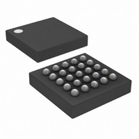
DS1862AB+ Maxim Integrated Products, DS1862AB+ Datasheet - Page 32

DS1862AB+
Manufacturer Part Number
DS1862AB+
Description
IC LASR CTRLR 7CHAN 5.5V 25CSBGA
Manufacturer
Maxim Integrated Products
Type
Laser Diode Controller (Fiber Optic)r
Datasheet
1.DS1862ABTR.pdf
(42 pages)
Specifications of DS1862AB+
Data Rate
10Gbps
Number Of Channels
7
Voltage - Supply
2.9 V ~ 5.5 V
Current - Supply
3mA
Operating Temperature
-40°C ~ 100°C
Package / Case
25-CSBGA
Mounting Type
Surface Mount
Lead Free Status / RoHS Status
Lead free / RoHS Compliant
XFP Laser Control and Digital Diagnostic IC
DDh
DEh
DFh
E0h → FFh
Table 02h
80h → FFh
Table 03h
80h → C7h
Table 04h
80h → B8h
81h
82h
83h
84h
32
• LO MEM 6Eh EN ..............<R-all/W-Module><Shadowed Nonvolatile><00> If bit 5 is high, then bit 3 of 6Eh is
• AUX1/2 UNIT SEL ............<R-all/W-Module><Shadowed Nonvolatile><00> These two 4-bit values define what
• USER EE ..........................<R-all/W-Module><Shadowed Nonvolatile><00>
• USER EE ..........................<R-all/W-Module><Nonvolatile><00>
• USER EE ..........................<R-all/W-Host><Nonvolatile><00>
• LUT ..................................<R-Module/W-Module><Nonvolatile><00> These registers control the output
• BIAS SHIFT ......................<R-Module/W-Module><Shadowed Nonvolatile><0> This 4-bit value in <7:4> defines
• TX-P SHIFT .......................<R-Module/W-Module><Shadowed Nonvolatile><0> This 4-bit value in <3:0> defines
• RX-P SHIFT ......................<R-Module/W-Module><Shadowed Nonvolatile><0> This 4-bit value in <7:4> defines
• AUX1 SHIFT .....................<R-Module/W-Module><Shadowed Nonvolatile><0> This 4-bit value in <3:0> defines
• AUX2 SHIFT .....................<R-Module/W-Module><Shadowed Nonvolatile><0> This 4-bit value in <7:4> defines
• APC REF COARSE ...........<R-Module/W-Module><Shadowed Nonvolatile><00> This 8-bit value sets the
______________________________________________________________________________________
not masked. If bit 6 is high, then bit 6 of 6Eh is not masked. Bit 0 is the Lock_Bit. If
set, Lower Memory address 01h, bit 0 is writable.
is being measured on AUX1MON and AUX2MON. MSB is AUX1MON unit select and
LSB is AUX2MON unit select. See Table 5 for more details.
current on MODSET as a function of temperature.
how many right-shifts IBIASMON monitor channel receives. The MSB is bit 7.
how many right-shifts TX-P (BMD) monitor channel receives. The MSB is bit 3.
how many right-shifts RX-P (RSSI) monitor channel receives. The MSB is bit 7.
how many right-shifts AUX1MON monitor channel receives. The MSB is bit 3.
how many right-shifts AUX2MON monitor channel receives. The MSB is bit 7.
coarse APC current on BMD.


