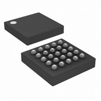
DS1862AB+ Maxim Integrated Products, DS1862AB+ Datasheet - Page 15

DS1862AB+
Manufacturer Part Number
DS1862AB+
Description
IC LASR CTRLR 7CHAN 5.5V 25CSBGA
Manufacturer
Maxim Integrated Products
Type
Laser Diode Controller (Fiber Optic)r
Datasheet
1.DS1862ABTR.pdf
(42 pages)
Specifications of DS1862AB+
Data Rate
10Gbps
Number Of Channels
7
Voltage - Supply
2.9 V ~ 5.5 V
Current - Supply
3mA
Operating Temperature
-40°C ~ 100°C
Package / Case
25-CSBGA
Mounting Type
Surface Mount
Lead Free Status / RoHS Status
Lead free / RoHS Compliant
The DS1862A’s block diagram is described in detail
within the following sections and memory map/memory
description.
The DS1862A’s APC is accomplished by closed-loop
adjustment of the bias current (BIASSET) until the feed-
back current (BMD) from a photodiode matches the
value determined by the APC registers. The relation-
ship between the APC register and I
where APC
84h that controls the coarse BMD current, and
APC
current.
The BMD pin appears as a voltage source in series
with two resistors. The overall equivalent resistance of
the BMD input pin can be closely approximated by the
plot in Figure 8. The voltage that appears on the BMD
pin, assuming no external current load, is 1.2V if BMD
is in sink-current mode (SRC_SINK_B = 0) or 2.0V if
BMD is set to source current (SRC_SINK_B = 1). This
allows the photodiode to be referenced to either V
or GND. When the control loop is at steady state, the
BMD current setting matches the current that is mea-
sured by the I
tance. During a transient period, the DS1862A adjusts
the current drive on the BIASSET pin to bring the loop
Figure 8. Approximate Model of the BMD Input
F
<1:0> is the 2-bit value that controls the fine BMD
XFP Laser Control and Digital Diagnostic IC
C
I
BMD
<7:0> is the 8-bit value in Table 04h, Byte
BMD RESISTANCE vs. BMD SUPPLY CURRENT
600
584
565
546
527
508
489
470
0
Automatic Power Control (APC)
BMD
(1.464μA x APC
0
= 5.859μA x APC
______________________________________________________________________________________
0.25 0.50 0.75 1.00
voltage across the internal resis-
Detailed Description
I
BMD
F
(mA)
<1:0>)
C
<7:0> +
BMD
1.25
is given by:
1.50
CC3
into steady state. The DS1862A is designed to support
loop gains of 1/20 to 10.
On power-up, the BMD current ramps up to the previ-
ously saved current setting in EEPROM APC registers.
While operating, the DS1862A monitors the BMD cur-
rent. If it begins to deviate from the desired (set) I
value, the current on the BIASSET pin is again adjusted
to compensate.
The DS1862A uses a temperature indexed lookup table
(LUT) to control the extinction ratio. The MODSET pin is
capable of sinking current based on the 8-bit binary value
that is controlling it. The DS1862A also features a user-
configurable current range to increase extinction ratio
resolution. Five current ranges, as described in Table 1,
are available to control the current entering MODSET.
Table 1. Selectable Current Ranges for
MODSET
TABLE 04h, BYTE 86h<2:0>
LUT CURRENT RANGE
000
001
010
011
100
V
BMD
CONTROLLED BY THE
R
SRC_SINK_B BIT IN
BMD
NOTE: V
Extinction Ratio Control
TABLE 04h.
VOLTAGE
I
BMD
BMD
Lookup Table (LUT)
IS
CURRENT RANGE
0 to 1200
0 to 150
0 to 300
0 to 600
0 to 75
(μA)
BMD
BMD
15


