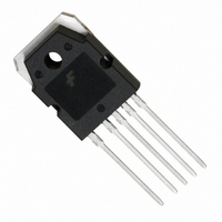
FS7M0880YDTU Fairchild Semiconductor, FS7M0880YDTU Datasheet - Page 5

FS7M0880YDTU
Manufacturer Part Number
FS7M0880YDTU
Description
IC SWIT PWM CM OVP UVLO HV TO3P
Manufacturer
Fairchild Semiconductor
Specifications of FS7M0880YDTU
Output Isolation
Isolated
Frequency Range
60 ~ 72kHz
Voltage - Input
9 ~ 30 V
Voltage - Output
800V
Power (watts)
190W
Operating Temperature
25°C ~ 150°C
Package / Case
TO-3P-5
Power Switch Family
FS7M0880
Input Voltage
-0.3 to 8.1V
Power Switch On Resistance
1.2Ohm
Output Current
6A
Number Of Outputs
Single
Mounting
Through Hole
Supply Current
8mA
Package Type
TO-3P
Operating Temperature (min)
-25C
Operating Temperature (max)
85C
Operating Temperature Classification
Commercial
Pin Count
5 +Tab
Power Dissipation
190W
Lead Free Status / RoHS Status
Lead free / RoHS Compliant
Other names
FS7M0880YDTU_NL
FS7M0880YDTU_NL
FS7M0880YDTU_NL
Available stocks
Company
Part Number
Manufacturer
Quantity
Price
Company:
Part Number:
FS7M0880YDTU
Manufacturer:
FSC
Quantity:
48 780
Company:
Part Number:
FS7M0880YDTU
Manufacturer:
FSC
Quantity:
20
Company:
Part Number:
FS7M0880YDTU
Manufacturer:
FUJI
Quantity:
20 000
Company:
Part Number:
FS7M0880YDTU
Manufacturer:
Fairchi/ON
Quantity:
32 000
Part Number:
FS7M0880YDTU
Manufacturer:
FAIRCHILD/仙童
Quantity:
20 000
Block Diagram
It can be divided into several large, functional sections:
under voltage lockout circuitry (UVLO); reference voltage;
oscillator (OSC); pulse width modulation (PWM) block;
protection circuits; and gate driving circuits.
Start Up
Input voltage range: 85 ~ 265 V (AC)
When Vac is minimum and it is started by the DC Link bulk
capacitor, the starting resistance is calculated as follows:
When Vac is maximum and it is started by the DC Link Bulk
capacitor, the power loss is calculated as follows:
When it is started by the one-phase of the AC-Lines and Vac
is minimum, the starting resistance is calculated as follows:
When it is started bythe one-phase of the AC_Line and Vac
is maximum, the power loss is calculated as follows:
The starting current across the starting resistor charges the
SPS V
starting voltage, the SPS starts to switch the built-in
MOSFET. Once it starts, the current in the SPS control IC
abruptly is increased to 7mA, makes it difficult to operate
with the current through the starting resistor. Therefore, after
it starts, the auxiliary winding of the transformer supplies
most of the power to SPS. It is best to use an appropriate size
V
too large, the starting time can be delayed. This operation is
Ploss
CC
R start
Va
power capacitor, generally about 33 F, because if it is
CC
=
=
capacitor. When the V
------------------------------------- -
85 2 15
-------------------------- -
265 2 15
Va rms
R
80 A
1.3M
Start
P
loss
–
265V
–
85V
=
=
=
=
=
=
38M
=
2 85 2 15
--------------------------------------- -
2
82 mW
177V Vp
Va rms 2
-------------------------- -
1.3M
------
2
=
Rstart
1
0.1 W
∫
2
o
CC
Vp
–
=
becomes greater than the
sin
=
265 2
----------------- -
t
177 2
38M
–
80 A
15
2
dt
described in Fig 2. Although V
9V during operation, it should be set such that OVP does not
execute during an overload condition. For a full load, about
18~20V is appropriate for the V
about 13~14V.
Protection
The FPS has several self-protection circuits, which can
operate without additional external components, thereby
acquiring reliability without increase in cost. After a
protection circuit comes on, it can completely stop the SMPS
until the cutoff AC power is reconnected (Latch Mode
Protection) or it can make the SMPS operate above the
UVLO by unlatching the control voltage below the ULVO
(Auto Restart Mode Protection).
These two operations are user-command operations, so the
user can select the
operation from the IC or by carefully controlling circuit
constants. The operation and applications for each protection
are described below.
Over Load Protection
In abnormal status of SMPS over load is distinguished from
load short. This happens when a load exceeds a pre-set load
during normal operation. That is, the FPS overload
protection circuit stops the FPS if an instantaneous load
increases and becomes greater than 50W during normal
operation, when the maximum SMPS output had been
pre-set to 30W. In this type of protection, the protection
Figure 1. Detail of the undervoltage lockout (UVLO)
thereby maintaining the SenseFET at turnoff.
Icc
[mA]
0.1
circuitry in a Fairchild Power Switch. The gate
20
7
operating circuit holds in a low state during UVL
Power On Reset
Range
Figure 2. Start-up Waveform
6V
Fig 2 < Start-up Waveform >
9V
15V
CC
CC
only needs to be set above
voltage and for no load,
UVLO
UVLO
UVLO
UVLO
Vz
[V]
Vcc
FS7M0880
5


