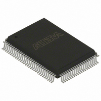
EPC4QI100 Altera, EPC4QI100 Datasheet - Page 38

EPC4QI100
Manufacturer Part Number
EPC4QI100
Description
IC CONFIG DEVICE 4MBIT 100-PQFP
Manufacturer
Altera
Series
EPCr
Datasheet
1.EPC4QI100N.pdf
(116 pages)
Specifications of EPC4QI100
Programmable Type
In System Programmable
Memory Size
4Mb
Voltage - Supply
3 V ~ 3.6 V
Operating Temperature
-40°C ~ 85°C
Package / Case
100-MQFP, 100-PQFP
Lead Free Status / RoHS Status
Contains lead / RoHS non-compliant
Other names
544-2189
Available stocks
Company
Part Number
Manufacturer
Quantity
Price
Company:
Part Number:
EPC4QI100
Manufacturer:
ALTERA
Quantity:
1
Part Number:
EPC4QI100
Manufacturer:
ALTERA/阿尔特拉
Quantity:
20 000
Company:
Part Number:
EPC4QI100N
Manufacturer:
ALTERA
Quantity:
300
Part Number:
EPC4QI100N
Manufacturer:
ALTERA/阿尔特拉
Quantity:
20 000
2–2
Concurrent Configuration Using n-Bit PS Modes
Configuration Handbook (Complete Two-Volume Set)
f
1
For more information about additional enhanced configuration devices, refer to the
Process Change Notification
EPC4, EPC8 and EPC16 Enhanced Configuration Devices
Memory Based EPC4, EPC8, and EPC16 Devices
The n-bit (n = 1, 2, 4, or 8) PS configuration mode allows enhanced configuration
devices to concurrently configure SRAM-based devices or device chains. In addition,
these devices do not have to be the same device family or density; they can be any
combination of Altera SRAM-based devices. An individual enhanced configuration
device DATA line is available for each targeted device. Each DATA line can also feed a
daisy chain of devices.
The Quartus II software only allows the selection of n-bit PS configuration modes.
However, you can use these modes to configure any number of devices from 1 to 8.
When configuring SRAM-based devices using n-bit PS modes, use
the appropriate configuration mode for the fastest configuration times.
Mode selection has an impact on the amount of memory used, as described in
“Calculating the Size of Configuration Space” on page
Table 2–1. Recommended Configuration Using
For example, if you configure three SRAM-based devices, you would use the 4-bit PS
mode. For the DATA0, DATA1, and DATA2 lines, the corresponding .sof data will be
transmitted from the configuration device to the SRAM-based PLD. For DATA3, you
can leave the corresponding Bit3 line blank in the Quartus II software. On the
printed circuit board (PCB), leave the DATA3 line from the enhanced configuration
device unconnected.
window (Tools menu) setup for this scheme.
Note to
(1) Assume that each DATA line is only configuring one device, not a daisy chain of devices.
Number of Devices
Table
2–1:
1
2
3
4
5
6
7
8
Figure 2–1
(1)
PCN0506: Addition of Intel Flash Memory As Source For
shows the Quartus II Convert Programming Files
n -Bit PS Modes
Recommended Configuration Mode
white paper.
Chapter 2: Altera Enhanced Configuration Devices
and the
2–14.
1-bit PS
2-bit PS
4-bit PS
4-bit PS
8-bit PS
8-bit PS
8-bit PS
8-bit PS
© December 2009 Altera Corporation
Using the Intel Flash
Table 2–1
Concurrent Configuration
to select


