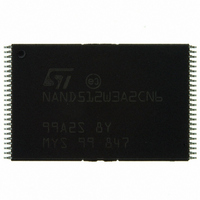
NAND512W3A2CN6E NUMONYX, NAND512W3A2CN6E Datasheet - Page 25

NAND512W3A2CN6E
Manufacturer Part Number
NAND512W3A2CN6E
Description
IC FLASH 512MBIT 48TSOP
Manufacturer
NUMONYX
Datasheet
1.NAND512R3A2CZA6E.pdf
(55 pages)
Specifications of NAND512W3A2CN6E
Format - Memory
FLASH
Memory Type
FLASH - Nand
Memory Size
512M (64M x 8)
Interface
Parallel
Voltage - Supply
2.7 V ~ 3.6 V
Operating Temperature
-40°C ~ 85°C
Package / Case
48-TSOP
Cell Type
NAND
Density
512Mb
Access Time (max)
12us
Interface Type
Parallel
Boot Type
Not Required
Address Bus
26b
Operating Supply Voltage (typ)
3/3.3V
Operating Temp Range
-40C to 85C
Package Type
TSOP
Program/erase Volt (typ)
2.7 to 3.6V
Sync/async
Asynchronous
Operating Temperature Classification
Industrial
Operating Supply Voltage (min)
2.7V
Operating Supply Voltage (max)
3.6V
Word Size
8b
Number Of Words
64M
Supply Current
20mA
Mounting
Surface Mount
Pin Count
48
Lead Free Status / RoHS Status
Lead free / RoHS Compliant
Speed
-
Lead Free Status / RoHS Status
Lead free / RoHS Compliant, Compliant
Available stocks
Company
Part Number
Manufacturer
Quantity
Price
Company:
Part Number:
NAND512W3A2CN6E
Manufacturer:
MICRON
Quantity:
1 500
Part Number:
NAND512W3A2CN6E
Manufacturer:
ST
Quantity:
20 000
NAND512-A2C
6.3
Figure 13. Page program operation
1. Before starting a page program operation a pointer operation can be performed. Refer to
details.
RB
I/O
Page program
The page program operation is the standard operation to program data to the memory array.
The main area of the memory array is programmed by page, however partial page
programming is allowed where any number of bytes (1 to 528) or words (1 to 264) can be
programmed.
The maximum number of consecutive partial page program operations allowed in the same
page is three. After exceeding this a Block Erase command must be issued before any
further program operations can take place in that page.
Before starting a page program operation a pointer operation can be performed to point to
the area to be programmed. Refer to the
details.
Each page program operation consists of five steps (see
1.
2.
3.
4.
5.
Once the program operation has started the status register can be read using the Read
Status Register command. During program operations the status register only flags errors
for bits set to '1' that have not been successfully programmed to '0'.
During the program operation, only the Read Status Register and Reset commands are
accepted, all other commands are ignored.
Once the program operation has completed the P/E/R controller bit SR6 is set to ‘1’ and the
Ready/Busy signal goes High.
The device remains in read status register mode until another valid command is written to
the command interface.
Page Program
Setup Code
One bus cycle is required to setup the Page Program command
Four bus cycles are then required to input the program address (refer to
Table
The data is then input (up to 528 bytes/264 words) and loaded into the page buffer
One bus cycle is required to issue the confirm command to start the P/E/R controller
The P/E/R controller then programs the data into the array.
80h
7)
Address Inputs
Data Input
Section 6.1: Pointer operations
(Program Busy time)
Confirm
Code
10h
tBLBH2
Figure
Section 6.1: Pointer operations
Busy
13):
Read Status Register
Device operations
70h
and
Figure 8
Table 6
SR0
ai07566
and
for
for
25/55


