AT25DF161-MH-Y Atmel, AT25DF161-MH-Y Datasheet - Page 11
AT25DF161-MH-Y
Manufacturer Part Number
AT25DF161-MH-Y
Description
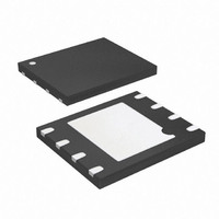
IC FLASH 16MBIT 100MHZ 8UDFN
Manufacturer
Atmel
Datasheet
1.AT25DF161-SH-B.pdf
(52 pages)
Specifications of AT25DF161-MH-Y
Format - Memory
FLASH
Memory Type
DataFLASH
Memory Size
16M (2M x 8)
Speed
100MHz
Interface
SPI, RapidS
Voltage - Supply
2.7 V ~ 3.6 V
Operating Temperature
-40°C ~ 85°C
Package / Case
8-UDFN
Lead Free Status / RoHS Status
Lead free / RoHS Compliant
Available stocks
Company
Part Number
Manufacturer
Quantity
Price

Part Number:
AT25DF161-MH-Y
Manufacturer:
ATMEL/爱特梅尔
Quantity:
20 000


3687E–DFLASH–11/10
8.2
the device will return to the idle state once the CS pin has been deasserted. The WEL bit in the Status Register will be
reset back to the logical “0” state if the program cycle aborts due to an incomplete address being sent, an incomplete
byte of data being sent, the CS pin being deasserted on uneven byte boundaries, or because the memory location to be
programmed is protected or locked down.
While the device is programming, the Status Register can be read and will indicate that the device is busy. For faster
throughput, it is recommended that the Status Register be polled rather than waiting the t
data bytes have finished programming. At some point before the program cycle completes, the WEL bit in the Status
Register will be reset back to the logical “0” state.
The device also incorporates an intelligent programming algorithm that can detect when a byte location fails to program
properly. If a programming error arises, it will be indicated by the EPE bit in the Status Register.
Figure 8-1.
Figure 8-2.
Dual-Input Byte/Page Program
The Dual-Input Byte/Page Program command is similar to the standard Byte/Page Program command and can be used to
program anywhere from a single byte of data up to 256-bytes of data into previously erased memory locations. Unlike the
standard Byte/Page Program command, however, the Dual-Input Byte/Page Program command allows two bits of data to
be clocked into the device on every clock cycle rather than just one.
Before the Dual-Input Byte/Page Program command can be started, the Write Enable command must have been
previously issued to the device (see
Register to a logical “1” state. To perform a Dual-Input Byte/Page Program command, an opcode of A2h must be clocked
SCK
SCK
SO
SO
CS
CS
SI
SI
Byte Program
Page Program
“Write Enable” on page
18) to set the Write Enable Latch (WEL) bit of the Status
BP
or t
Atmel AT25DF161
PP
time to determine if the
11
Related parts for AT25DF161-MH-Y
Image
Part Number
Description
Manufacturer
Datasheet
Request
R

Part Number:
Description:
IC FLASH 16MBIT 100MHZ 8SOIC
Manufacturer:
Atmel
Datasheet:

Part Number:
Description:
8-bit Atmel Microcontrollers
Manufacturer:
ATMEL [ATMEL Corporation]
Datasheet:
Part Number:
Description:
IC FLASH 16MBIT 100MHZ 8SOIC
Manufacturer:
Atmel
Datasheet:
Part Number:
Description:
IC FLASH 16MBIT 100MHZ 8SOIC
Manufacturer:
Atmel
Datasheet:
Part Number:
Description:
IC FLASH 16MBIT 100MHZ 8SOIC
Manufacturer:
Atmel
Datasheet:

Part Number:
Description:
IC FLASH 16MBIT 100MHZ 8UDFN
Manufacturer:
Atmel
Datasheet:

Part Number:
Description:
16-megabit 2.7-volt Minimum Spi Serial Flash Memory
Manufacturer:
ATMEL Corporation
Datasheet:

Part Number:
Description:
DEV KIT FOR AVR/AVR32
Manufacturer:
Atmel
Datasheet:
Part Number:
Description:
INTERVAL AND WIPE/WASH WIPER CONTROL IC WITH DELAY
Manufacturer:
ATMEL Corporation
Datasheet:
Part Number:
Description:
Low-Voltage Voice-Switched IC for Hands-Free Operation
Manufacturer:
ATMEL Corporation
Datasheet:
Part Number:
Description:
MONOLITHIC INTEGRATED FEATUREPHONE CIRCUIT
Manufacturer:
ATMEL Corporation
Datasheet:
Part Number:
Description:
AM-FM Receiver IC U4255BM-M
Manufacturer:
ATMEL Corporation
Datasheet:
Part Number:
Description:
Monolithic Integrated Feature Phone Circuit
Manufacturer:
ATMEL Corporation
Datasheet: